4.5 Connecting to the Part handler (Handler Interface)
4-22 ZM2376
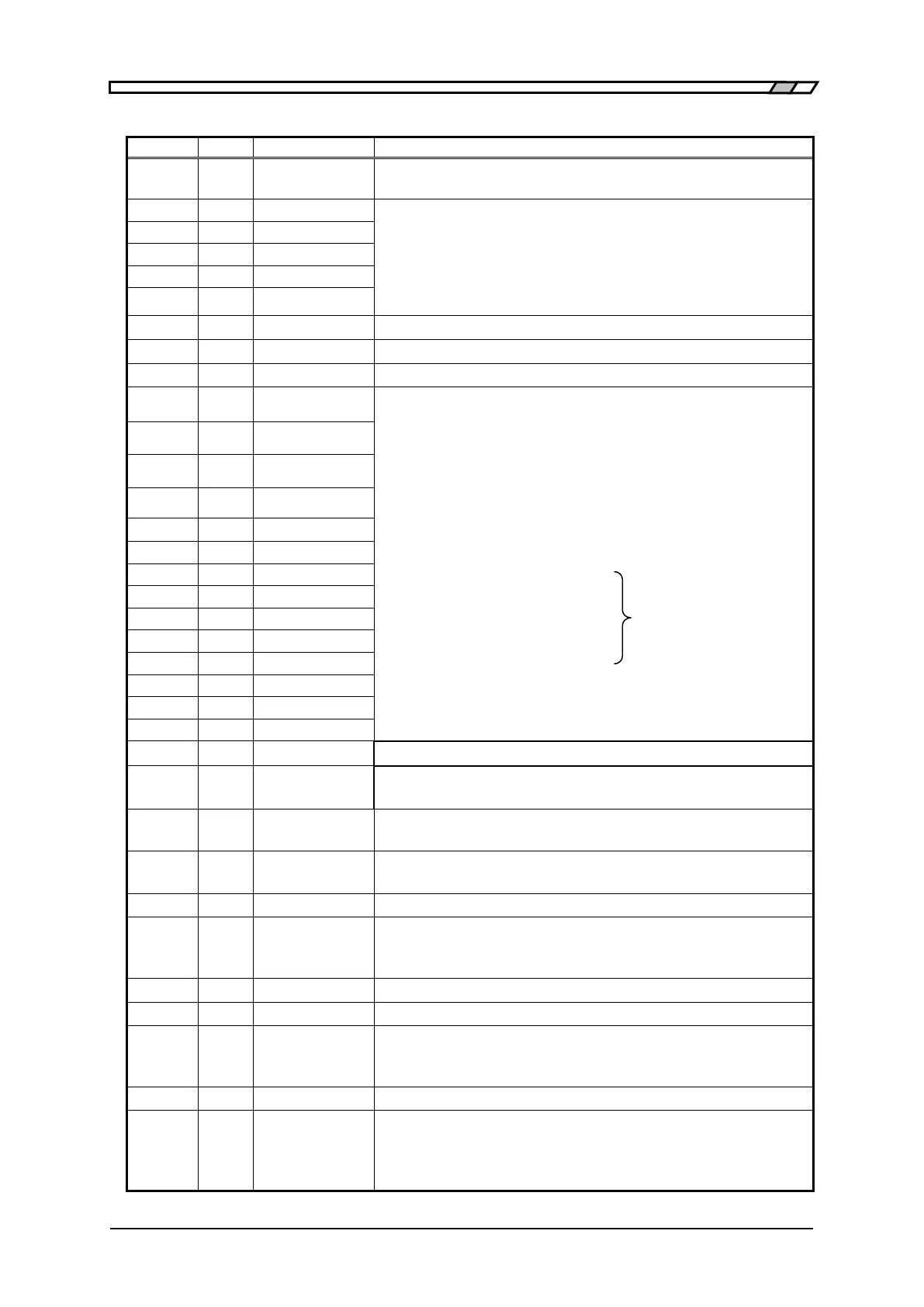
Table 4–4 Functions of handler interface signal
External trigger signal (rising edge).
Can be switched into falling edge.
Setting/correction value memory selection signal (Binary)
When /RCL-VALID is 1 (low level) and trigger source is external (Ext):
once the external trigger signal of Pin No.1 is received, the memory
specified by this signal allows the setting and correction value to be
recalled and measurement is conducted under those conditions. Recall of
memory number out of the range may result in an error.
Not in use. Do not connect anything.
Not in use. Do not connect anything.
It shows that the memory selection signal is valid.
/BIN1 to /BIN14: Bin sorting signal
/BIN10 to /BIN14 are output when Bin expansion is enabled besides
the limit comparison is disabled.
/NC: Contact failure or Low C
/PHI: primary parameter upper limit over signal
/PLO: primary parameter lower limit under signal
/NC, /PHI and /PLO are output only when Bin expansion is disabled
(default value).
/P-HI, /P-IN, /P-LO:
Primary parameter comparison
signal
/S-HI, /S-IN, /S-LO:
Secondary parameter
comparison signal
/IN: Primary/secondary total pass
comparison signal
When limit comparison is
enabled, Bin sorting signals
of “/BIN1 to/BIN14” are
output in place of /PHI and
/PLO.
Also for the limit comparison, /NC, /ERR, /OUT OF BINS (invert of /IN)
and /S-NG (/S-HI or /S-LO) are output.
Signal acquisition end signal. Once it becomes “1” (low level), it is
possible to switch into next DUT.
End of measurement signal. Once it becomes “1”(low level), the
comparison result become valid and it is possible to read.
Measurement error signal. It shows excessive voltage or current, contact
failure (NC), ALC failure or other errors.
Secondary parameter fail comparison signal
Key lock signal. Once it becomes “1”(low level), it disables all
key-operations of panel. It cannot be canceled through the panel or
remote control.
Not in use. Do not connect anything.
External DC power input (+5V to +24V)
External DC power input (common)
Each signal of handler interface is isolated from the case and operates
with the external DC power.
Internal DC power output (+5V)
Internal DC power output (common)
It is connected to the enclosure. To operate the Handler interface with the
Internal DC power source, make connection between EXT COM and INT
COM and also between EXT DCV and INT DCV.
 Loading...
