3.4 Connection of DUT
3-16 ZM2376
Measurement signals
Main specifications of measurement signals are as follows:
Signal level Voltage 10mVrms to 5Vrms (ALC possible)
Constant current 1µArms to 200mArms (range depends on
measurement range, etc.)
Max. 7.1Vpk also including DC bias is outputted.
Output impedance About 6Ω / 25Ω / 100Ω (depending on measurement range, frequency,
etc.)
Max. drive current About 200mArms
3.4.2 Connection to DUT
Connect ZM2376 and DUT with 4-terminal (4-terminal-pair) as shown below to avoid the influence
of contact resistance.
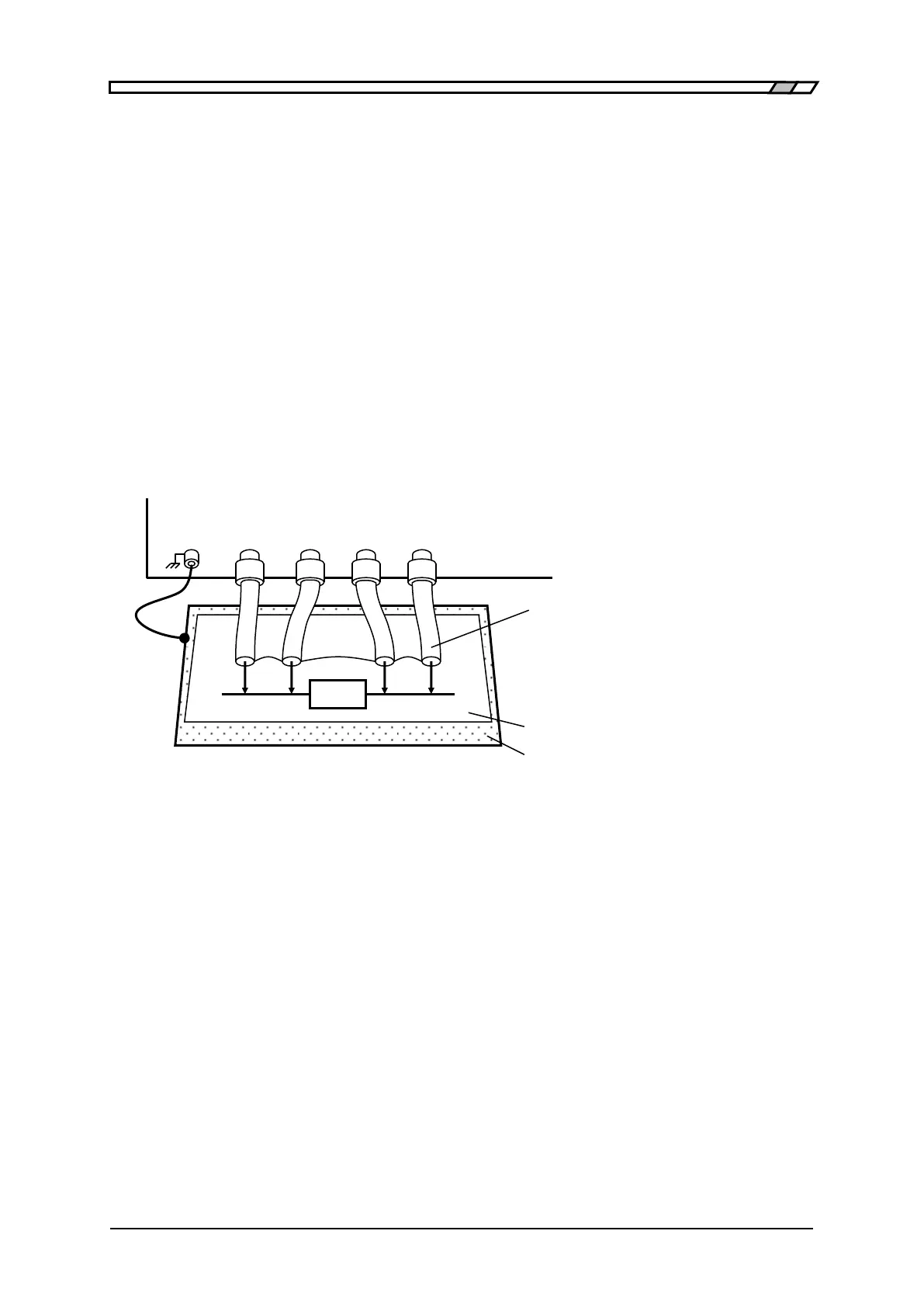
Figure 3-4 Connection to DUT
In the measurement of high impedance, shielding around the DUT can restrict variation of measured
value. In a simplified method, place an insulating plate on the top surface of ZM2376, and measure
the DUT on it.
The ZM2376 cannot measure the grounded DUT. Both ends of DUT must be both insulated from the
grounding.
When commercially available test fixture or test lead is used, refer to the instruction manual of these
products. The product in which the shields of respective terminals are not connected cannot be used
together with the ZM2376.
Use four coaxial cables having BNC
connector.
Connect 4 shields together on the
DUT side.
When the measured value is unstable due to a noise, lay a metallic plate connected to the
outer conductor (shields) of measurement cables or the case under the DUT for shielding.