4.11 Applying the DC Bias Current
4-51 ZM2376
4.11 Applying the DC Bias Current
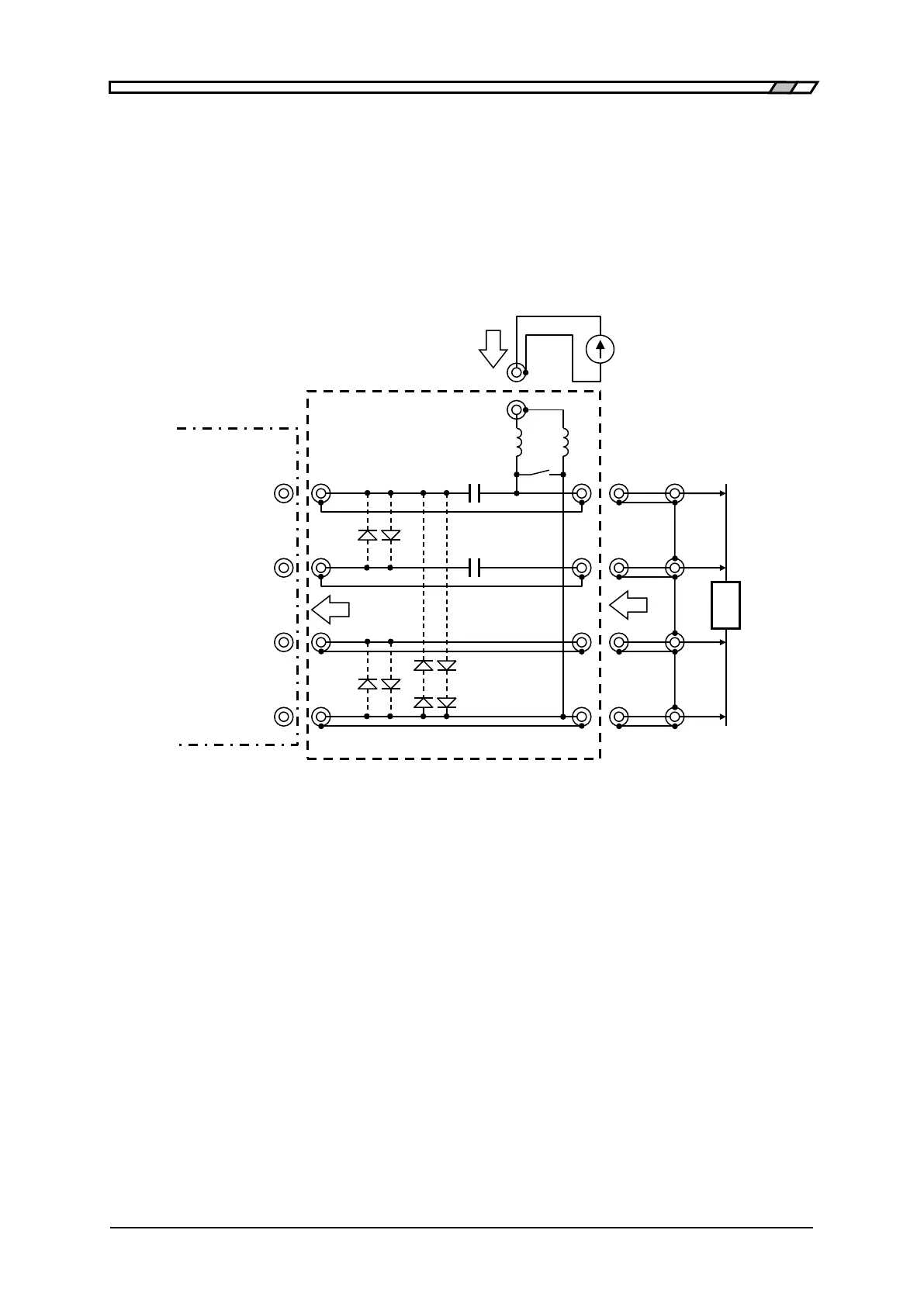
To flow the DC bias current in the inductor for measurement, you need a choke coil to reduce an
influence of the external power supply connected with DUT in parallel in addition to a DC blocking
circuit for applying the bias voltage and an external power to provide the bias current. Typical
measurement system is as follows.
Element value: Example when the measurement frequency is 1kHz or more.
C1=20µF (Film capacitor)
C2 = 1µF (Film capacitor)
Figure 4-10 Example of external current bias circuit
Usually, since the OPEN correction cannot be performed to remove an influence caused by the bias
current source, set the impedance of the choke coil L1 + L2 excessively larger than the impedance of
the DUT to reduce the measurement error.
The external power must be isolated from the ground. When the stray capacitance to grounding is
large, the measurement error may increase or the LCR meter may be unstable to disable the
measurement.
It is safe to lower the bias current to zero slowly and close the switch S1 before
connecting/disconnecting the DUT. The LCR meter may be damaged due to a high voltage caused by
the disconnected DUT. Set the protective diode. The rectifier diode, which has a serge current
susceptibility for preventing from damaging due to the bias current and also has a small reverse leak
 Loading...
