3.1 Panel Component Names and Functions
3-2 ZM2376
3.1 Panel Component Names and Functions
This section describes the names and functions of the components on the front and rear panel of
ZM2376.
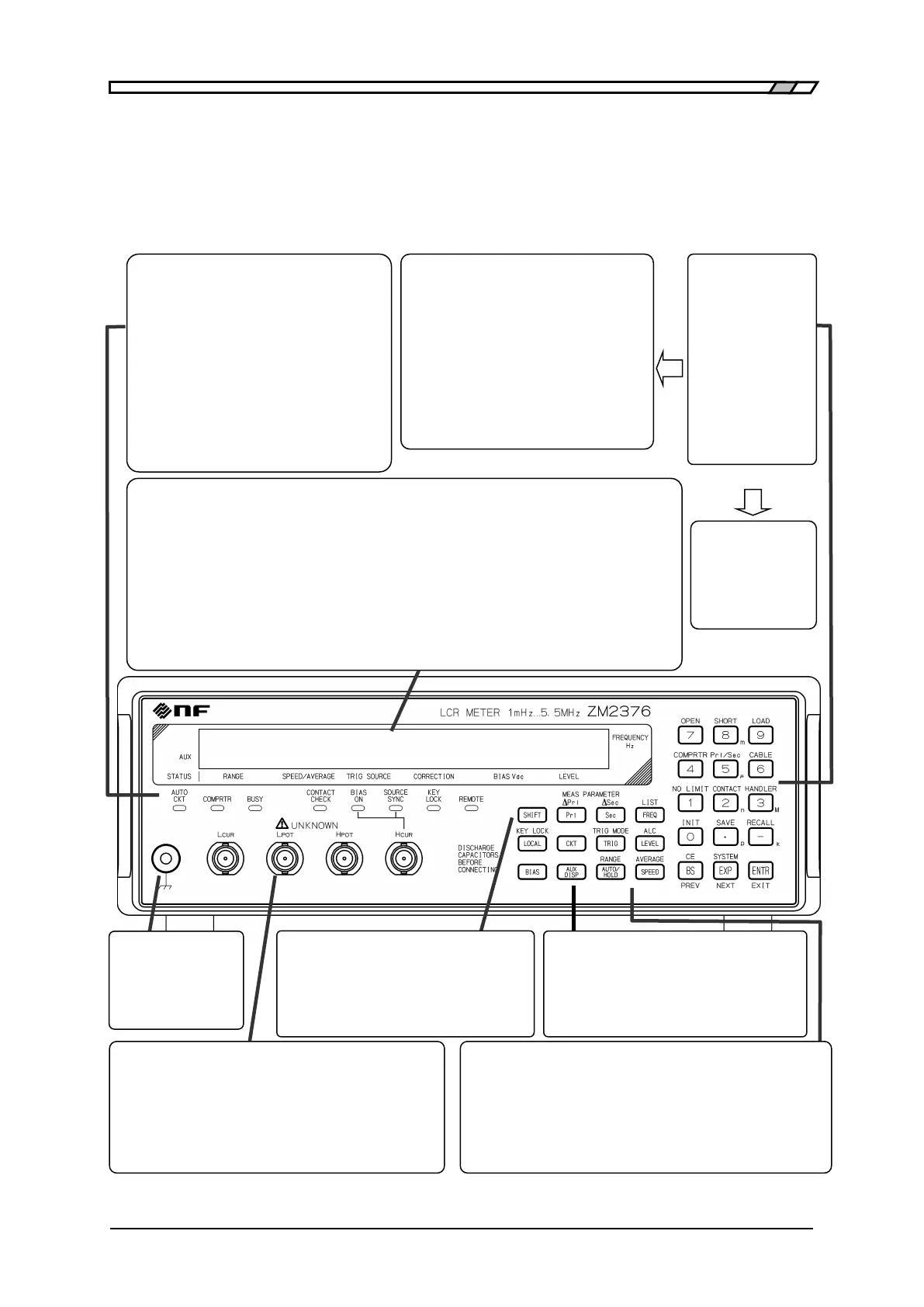
Figure 3-1 Front panel
Correction
OPEN, SHORT, LOAD, CABLE
Comparator/Handler interface
COMPRTR, Pri/Sec, NO LIMIT, HANDLER
Setting/correction value memory
SAVE, RECALL
Other operations
INIT Initialization
SYSTEM System setting
CONTACT Contact check setting
Status indicator lamps
Each lamp is lit in the following case.
AUTO CKT: When the automatic selection of
equivalent circuit is enabled
COMPRTR: When the comparator is enabled
BUSY: During measurement
CONTACT: When the contact check is enabled
CHECK
BIAS ON: During the DC bias voltage output
SOURCE: When the triggered drive is enabled
SYNC
KEY LOCK: When the key operation is disabled
REMOTE: During remote control
Display
40-character x 2-line LCD display.
1st line: Measured value (primary and secondary
parameters) and measurement frequency.
When the comparator is enabled, the comparison result
is also displayed.
(▲: > Upper limit, ▼: < Lower limit)
2nd line: Status, DC bias voltage,
measurement signal level.
The status can be switched to IV monitor, etc.
When detailed setting is made, the entire display is
used for the setting menu.
Status (2nd line)
RANGE: Auto / Hold and measurement
range
SPEED: FAST / MED / SLOW, etc.
AVERAGE: Averaging count
TRIG SOURCE: INT / MAN / EXT, etc.
CORRECTION: Op (OPEN)
Sh (SHORT)
Ld (LOAD)
(Cable length) 0m / 1m / 2m / 4m
Register keys
0 .. 9 Number
• Decimal point
- Negative sign
EXP Exponential part
( p n µ m k M)
BS(Back Space)
ENTR(Enter)
<Secondary function>
CE(Clear Entry)
Measurement
ground terminal
It is connected to
the enclosure, and
used to shield DUT.
Measurement Terminals
BNC connector comprising a set of 4-terminal-pair connected to
the device under test (DUT).
H
CUR
: Outputs signals to drive the DUT.
H
POT
, L
POT
: Measures the voltage applied to the DUT.
L
CUR
: Measures the current flowing in the DUT.
Connect all external conductors (shields) of 4 cables.
SHIFT key
Enables the secondary functions written above
each key.
LOCAL key
Restores local operation from remote state.
<Secondary function>
KEY LOCK: Disables key operations
Measurement conditions
setting keys <Secondary function>
FREQ: Sets the frequency ··············· LIST: Sets multi-measurement
LEVEL: Sets signal level .................... ALC: Sets constant voltage / Constant
current
SPEED: Sets measurement speed ..... AVERAGE: Sets averaging
TRIG: Manual trigger .......................... TRIG MODE: Sets trigger mode
AUTO/HOLD: Range auto/manual RANGE: Sets measurement range
BIAS: Sets DC bias
Display setting keys <Secondary function>
Pri: Selects primary parameter ∆Pri: Sets deviation
display
Sec: Selects secondary parameter ∆Sec: Sets deviation
display
CKT: Selects equivalent circuit
AUX DISP: Auxiliary display (status, etc. on 2nd line)