3.4 Connection of DUT
3-17 ZM2376
3.4.3 Precautions on Connection
Handling of shields
Connect the shields (outer conductor) of connection cables, 4 pieces together on the DUT side. The
current that flows from H
CUR
terminal through DUT to the L
CUR
terminal returns to the H
CUR
terminal
through the shield. Measurement will fail unless this return path is provided. To stabilize reference
potential in the voltage detection part, connect the voltage cable shield and the current cable shield.
Do not connect the connection cable shields to the ground. If grounded, a noise will mix in due to
electromagnetic coupling by a ground loop or common impedance coupling with other equipment.
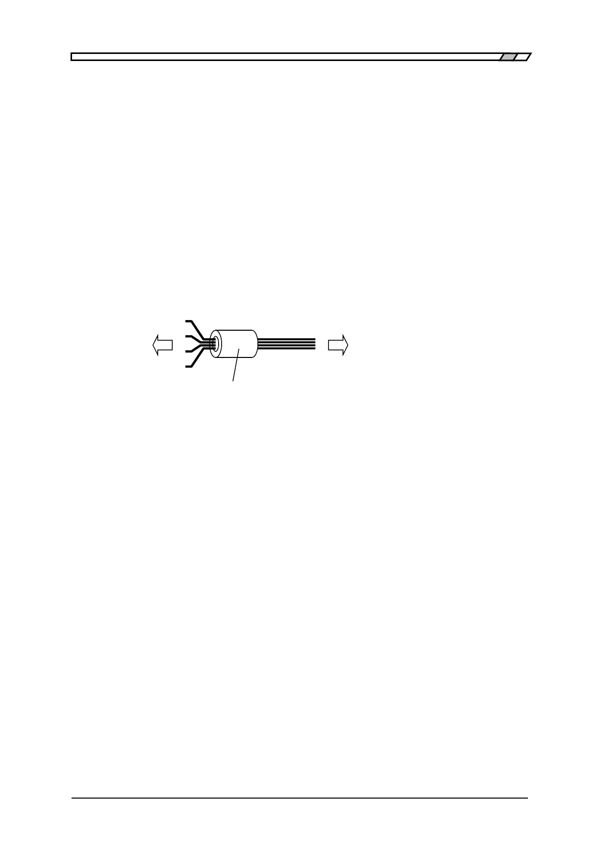
Electromagnetic interference prevention and electromagnetic susceptibility improvement
In the cable connection with the DUT, put four coaxial cables together in the vicinity of measurement
terminals of LCR meter, and attach the common mode choke. It can reduce high-frequency radiation
field disturbance received from the periphery, or reversely disturbance given to the periphery.
Measurement cables (ex. : 1.5D-2V × 4 pieces)
LCR meter DUT
Measurement Terminals
Common mode choke
(ex. : ESD-SR-250 NEC/TOKIN)
Selection of cables
In the measurement of low impedance such as capacitors having large capacitance, a voltage drop of
L
CUR
cable causes a common mode noise, increasing the measurement error. This error cannot be
corrected by the cable length correction. In a narrow measurement range, the error can be reduced by
the LOAD correction and it is therefore recommended to use thick and short current cables
(particularly for L
CUR
) so as to reduce the resistance of cable inner conductor to 0.5Ω or less per
cable. Note that the circuit (including probe resistance and contact resistance) between cables and
DUT has similar influence.
In the measurement of high impedance such as capacitors having small capacitance, using long
connection cables increases the error due to capacitance of the cables. This error can be corrected by
the cable length correction. However, correctable cables are coaxial cables of characteristic
impedance 50Ω (capacitance: about 105pF/m) having the specified length. When the cables used are
out of specification or when an error is large due to the DUT to earth capacitance, the error can be
reduced by the LOAD correction only in a narrow measurement range.
If cables substantially exceeding the specified length are used, or if DUT to earth capacitance is large,
the ZM2376 operation may become unstable or the measurement dispersions may become large due
to the influence of resistance value or capacitance of cable inner conductor. Note that particularly the
capacitance to ground on the L side is more likely to be influential. It may not be always true
depending on DUT or resistance of cables, but a total of capacitance of four connection cables and
capacitance to earth of DUT should be reduced to about 2000pF or less.
 Loading...
