1.4 Principle of Operation
1-6 ZM2376
1.4 Principle of Operation
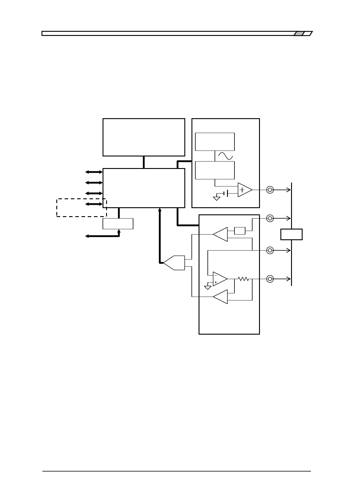
The ZM2376 gives sine wave signal from an internal oscillator to the DUT (Device Under Test). The
impedance bridge detects the current I flowing in DUT and the voltage V applied to DUT, and then the
main processor obtains the impedance Z (= V / I). The parameters such as inductance L, capacitance C,
resistance R, etc. are calculated from the impedance (magnitude, phase angle).
Figure 1-1 Block Diagram
Main Processor
According to the user’s operation, the main processor controls the oscillator and impedance bridge to
calculate the vector ratio from the voltage signal and current signal obtained from the DUT. Then, the
main processor makes necessary correction, and finally converts the data into the required parameter
to be displayed or output.
Panel
LCD Character Display,
Key & Lamp