4.5 Connecting to the Part handler (Handler Interface)
4-29 ZM2376
Input signal monitor
Numeric values appear while the status of Input signal line is being regarded as the negative logic
input.
When Trigger polarity = Negative
0 : High level, 1 : Low level
When Trigger polarity = Positive
0 : Low level, 1 : High level
0 .. 127 : /RCL6(MSB)../RCL0(LSB)
Displays 7 bits of negative logic as 3 digits of decimal.
0 : High level, 1 : Low level
0 : High level, 1 : Low level
Dummy output signal
You can control the output using numeric keys as follows.
Initializes all outputs to the status when the
comparator is disabled.
The comparison output is made into the low
level one at a time.
All are high level /OUT OF BINS
/BIN1...... /BIN14
/S-NG....All are high level
Bbb
bb = 00 : OUT OF BINS,
bb = 14 : BIN14,
bb = 15 : S-NG,
bb = 16 : All are high level
Ee
e = 0 : High level
e = 1 : Low level
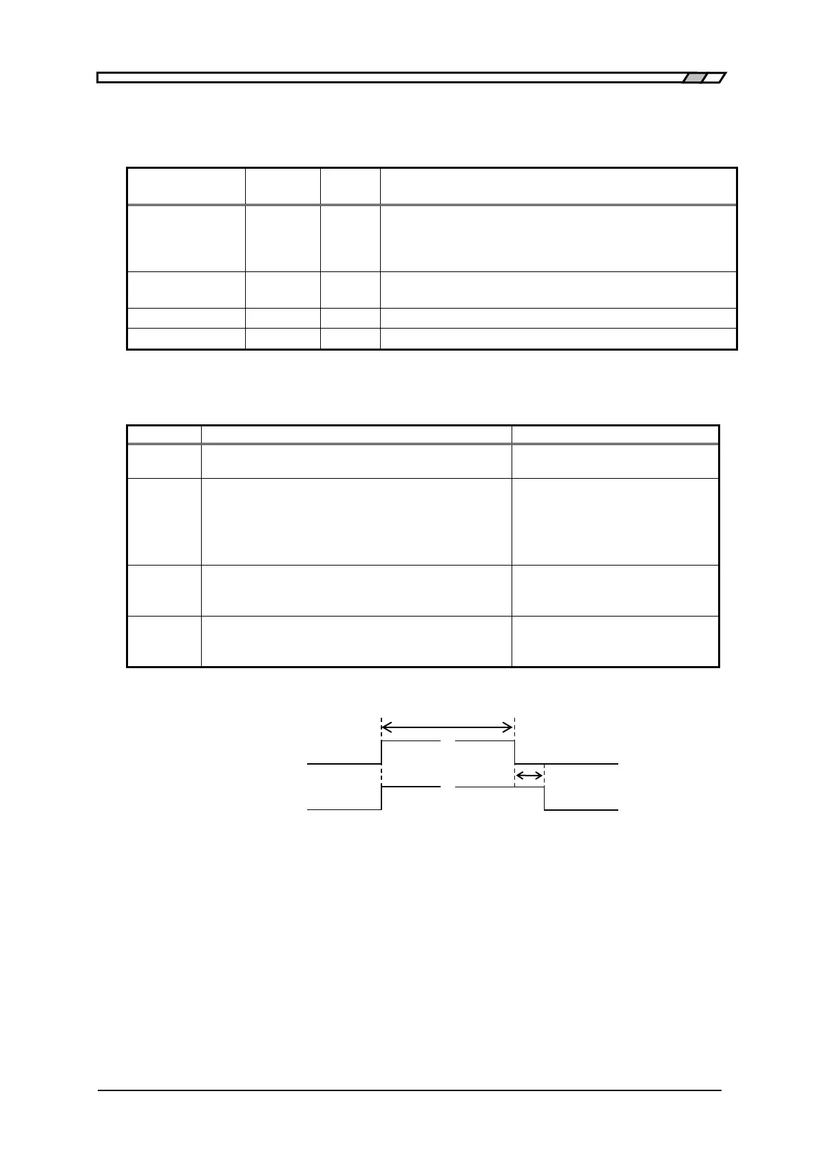
Changes /INDEX and /EOM as shown in the
figure below.
Mm (status of EOM)
m = 0 : High level
m = 1 : Low level
Approx 10ms
/INDEX
/EOM
Nearly simultaneously Approx 1ms
Figure 4–7 Dummy output timing