4.10 Applying the DC Bias Voltage
4-49 ZM2376
charge-/discharging.
Applying the high DC bias voltage
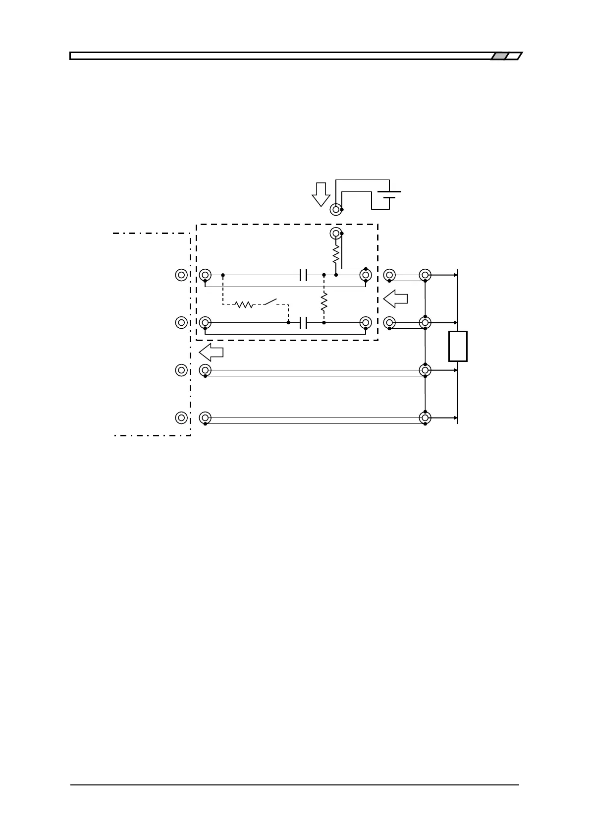
To apply the high bias voltage beyond 5V onto the DUT, external voltage source is required. In this
case, insert the capacitance in series between H
CUR
terminal and H
POT
terminal so that the DC voltage
and current may not run through the LCR meter.
Set the DC bias output of ZM2376 to OFF.
Element value: Example when frequency is 100Hz or more and minimum output impedance is
25Ω.
C1 = 200µF (Bipolar electrolytic capacitor)
C2 = 2.2µF (Film capacitor)
R1 = 1kΩ (R2=1kΩ , R3=1MΩ)
Figure 4-9 Example of external voltage bias circuit
C1 When the minimum output impedance is 100Ω or the measurement is not performed at low
frequency, the charge-/discharging time can be shorten by decreasing C1. When the
measurement is performed at lower frequency or you want to decrease the measurement
error at low impedance, increase C1.
C2 As with C1, select an optimum value depending on the frequency and so on. An additional
error of the phase increases at lower frequency. To reduce this error, increase C2. However,
it takes a longer settling time of the signal.
R1 R1 provides the charge-discharging current. R1 should be set to the value excessively
higher than the parallel value between the output impedance of LCR meter and the
impedance of DUT. Otherwise, the signal level applied to the DUT decreases, thereby
resulting in a large measurement error. In case of measurement of a large capacitance
 Loading...
