Green trafc light (option 2): OUT-TL3
One-way trafc light (option 3): OUT-TL2, OUT-TL3
Two-way trafc light (option 5): OUT-TL2, OUT-TL3
Door open indicator (option 6): OUT-TL1
Maintenance indicator (option 8): OUT-TL1
Flashing one-way trafc light (option 4): OUT-TL2, OUT-TL3
Status*: OUT-TL1, OUT-TL2, OUT-TL3
Electric lock*: OUT-TL2
Electric block*: OUT-TL2
Suction cup*: OUT-TL2
Courtesy light*: OUT-TL2
Radio channel 1*: OUT-TL3
Radio channel 2*: OUT-TL3
Radio channel 3*: OUT-TL3
Radio channel 4*: OUT-TL3
* Note1 - These functions can be activated only by using the Oview pro-
grammer.
ENCODER - input for the connection of the wiring of the electronic limit
switch (encoder)
PUSH BUTTONS - input for the connection of the External pushbuttons
present on the box cover.
IMPORTANT!
It is UNADVISABLE to connect any type of
device or accessory not expressly stated in this
instruction manual. The manufacturer declines
all liability for damage resulting from improper
use of the various devices of the system, not
conforming to the indications in this instruction
manual.
For more information contact the Nice customer
service department
3.4 - Description of the electrical connections to the power
board (g. 7)
MOTOR = output for the motor connection. In the version NDCC2301, to
control a motor with inverter it is necessary to connect the power supply of
the inverter on this output.
BRAKE = output for the connection of the electric brake (205 Vdc / max
25 W).
BOOST = output for the connection of the start-up condenser (model
NDCC2301 only).
LINE = input for the connection of the electric power supply.
L1-L2-L3: THREE-PHASE connection
L1-L3: MONO-PHASE connection
PE = input for the earthing connection of the control unit and motors.
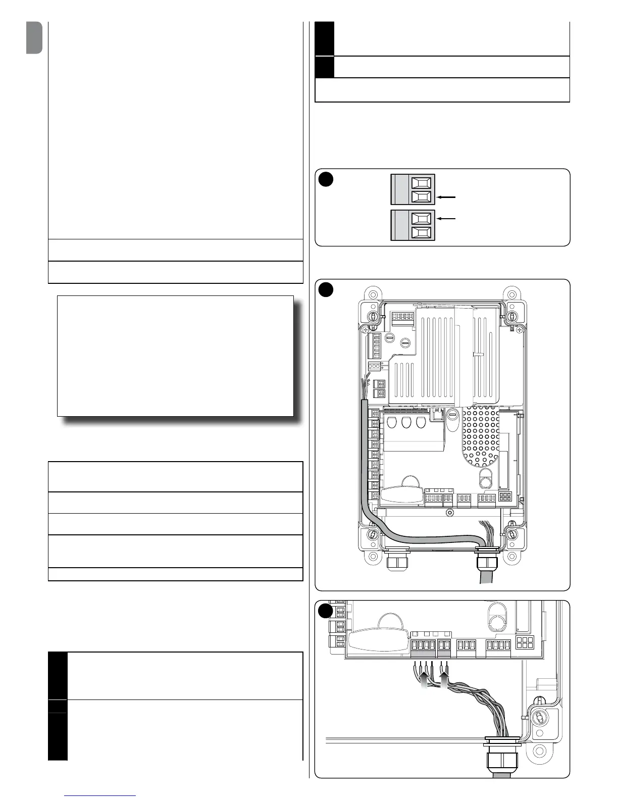
3.5 - Electrical connections of the control unit (g. 8)
CAUTION! – All electrical connections must be made with the unit
disconnected from the mains power supply.
After xing the box of the control unit and having arranged the holes for the
passage of electrical cables (see paragraph 2.4), make the electrical connections
as follows:
01. If not already present, rst connect the electrical power supply cable:
- for the models DIC4001, NDCC4002, NDCC4005 see paragraph
3.1
- for the model NDCC2301 see paragraph 3.2;
02. Then, connect the electrical cable coming from the motor:
- Three-phase motor with mechanical limit switch (g. 9 and 10)
- Three-phase motor with electronic limit switch (g. 11 and 12)
- Mono-phase motor with mechanical limit switch and start-up
condenser (g. 12 and 9)
- Mono-phase motor with electronic limit switch and start-up condenser
(g. 12 and 11)
- Three-phase motor with MEIN family inverter (g. 13 and 11)
03. Finally, connect the electrical cables of the various accessories present,
referring to g. 14 and paragraph 3.3.
Note – To facilitate cable connections, the terminals can be removed from
their seats.
3.6 - Connections of other devices to the control unit
If it is necessary to power additional devices included in the system, these can
be connected to the control unit on the terminals “S.S. (positive)” and “STOP
(negative)” (g. 14). The power supply voltage is 24 Vdc (-20% ÷ +20%), with
maximum available current 1A. Important - Do not connect inductive charges.

 Loading...