ELECTRICAL SYSTEM 74Service Manual – Advenger, 2800ST, 3800ST, BR 755, BR 855
Control board j1, j2, and j3 pin outs and test points
CAUTION!
Always take measurements at the end connectors for troubleshooting purposes. If readings taken there do not indicate the problem, check the
control board as a last resort as damage to the board may occur (see Caution statements in “Replacing Operator Control Panel” section).
Use a DVM and extended insulated probe tips (shown) to take the following measurements.
CAUTION!
Use only insulated test probes designed to backprobe. CONTROL BOARD IS POWERED during these tests.
Perform steps 2 and 3 of “Replacing Operator Control Panel” section, observing noted Caution statements.
J1 - Advenger / BR 755, 855 only - Brush deck lift actuator, squeegee lift actuator, chemical pump
To backprobe J1 for voltages, leave J1 connected to the control board.
Disc and Cylindrical
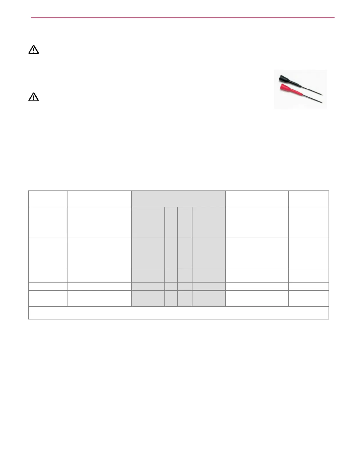
The followoing tables show the connector in the center, highlighted in gray with related informatin for the pin
off to either side.
Referenced to Measure J1 Measure Referenced to
B+
+24V to M4 for 3 sec. deck
downward travel
0V to M4 for 3 sec.
deck upward travel
ORN/BLK 5 10 WHT/GRN
0V to M3 for 3 sec.
squeegee down travel
24V to M3 for 3 sec.
squeegee up travel
B+
B+
0V to M4 for 3 sec. deck
downward travel
+24V to M4 for 3 sec.
deck upward travel
BLU 4 9 BLK/YEL
24V to M3 for 3 sec.
squeegee down travel
0V to M3 for 3 sec.
squeegee up travel
B+
B+ Not measurable using DVM BLU/GRY 3 8 BLK B-
2 7
B- Not measurable using DVM RED/YEL 1 6
Range of 24V measurements is 20 – 26 V
 Loading...