WHEEL DRIVE SYSTEM 67Service Manual – Advenger, 2800ST, 3800ST, BR 755, BR 855
Replacing the Drive Wheel Assembly
WARNING!
Park the machine on a dry at surface, turn the main key switch (J) to the Off position and disconnect the battery pack at the red Anderson
connectors inside the battery compartment.
1 Block the rear wheels.
2 Jack up the front of the machine as shown in “Jacking Points” section or use a hoist to lift up the front end of the machine.
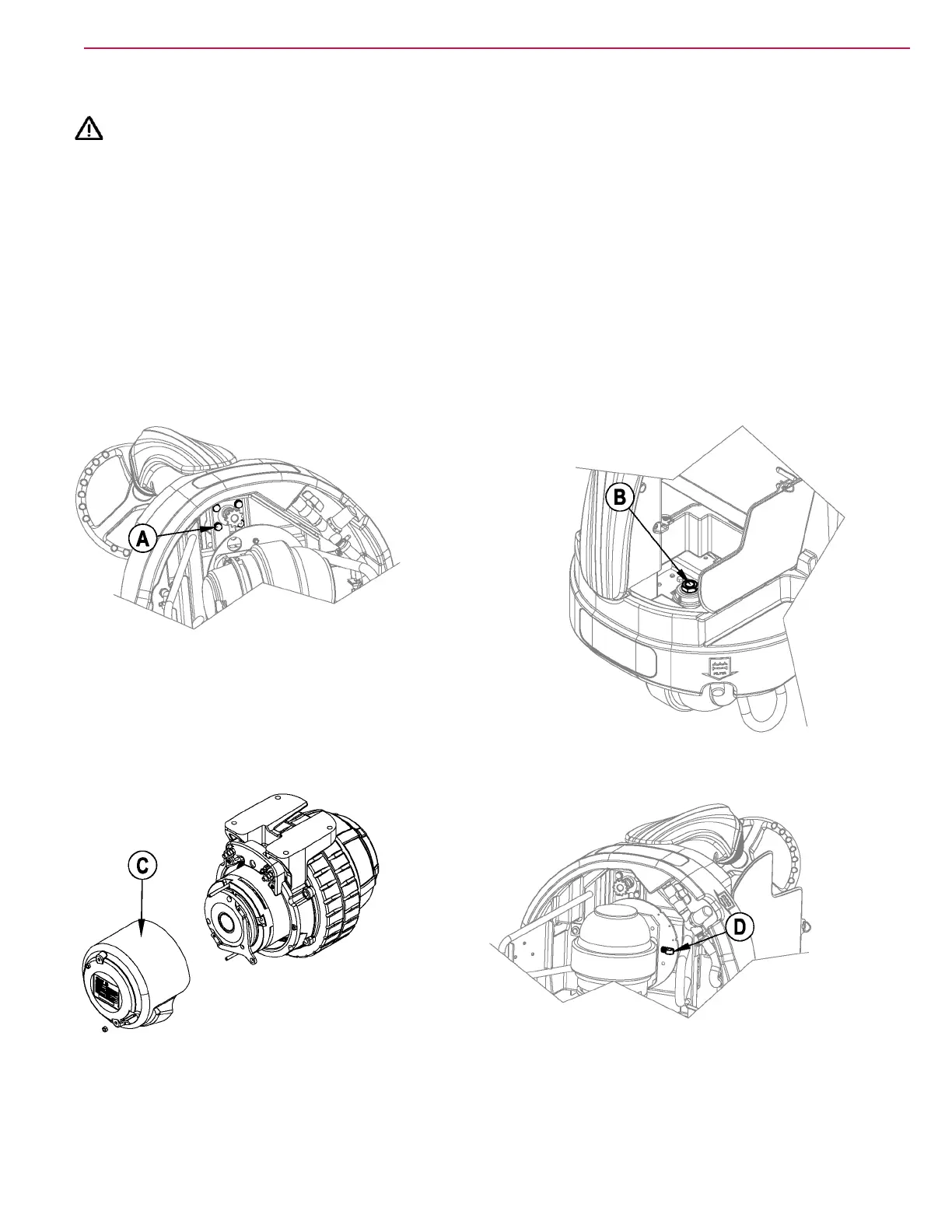
3 See Figure 31. Using a 17mm socket, loosen but don’t remove the four bolts (A) at the steering sprocket to allow the chain to release
some.
4 Using a 3/8” magnetic socket, remove the four bolts holding the charger in place, and move the charger over to the side.
5 See Figure 32. Using a 1 7/16” socket, remove the hex nut (B) at the top of the Spindle Weldment.
6 See Figure 33. Turn the Drive Wheel to the right and remove the motor wiring cover (C).
7 Using a 13mm and a 7mm socket, remove the nuts and wires from the drive motor.
8 See Figure 34. Turn the motor towards the left. Using a 7/16” socket and wrench, remove the P-clamp (D).
9 Jack up the front end of the machine enough to allow the wheel to slip free from the machine.
10 See Figure 31. Using a 17mm socket, remove the four bolts (A) at the top to free the motor from the Steering Plate.
FIGURE 31
FIGURE 32
FIGURE 33
FIGURE 34
 Loading...