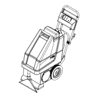
ELECTRICAL SYSTEM 75Service Manual – Advenger, 2800ST, 3800ST, BR 755, BR 855
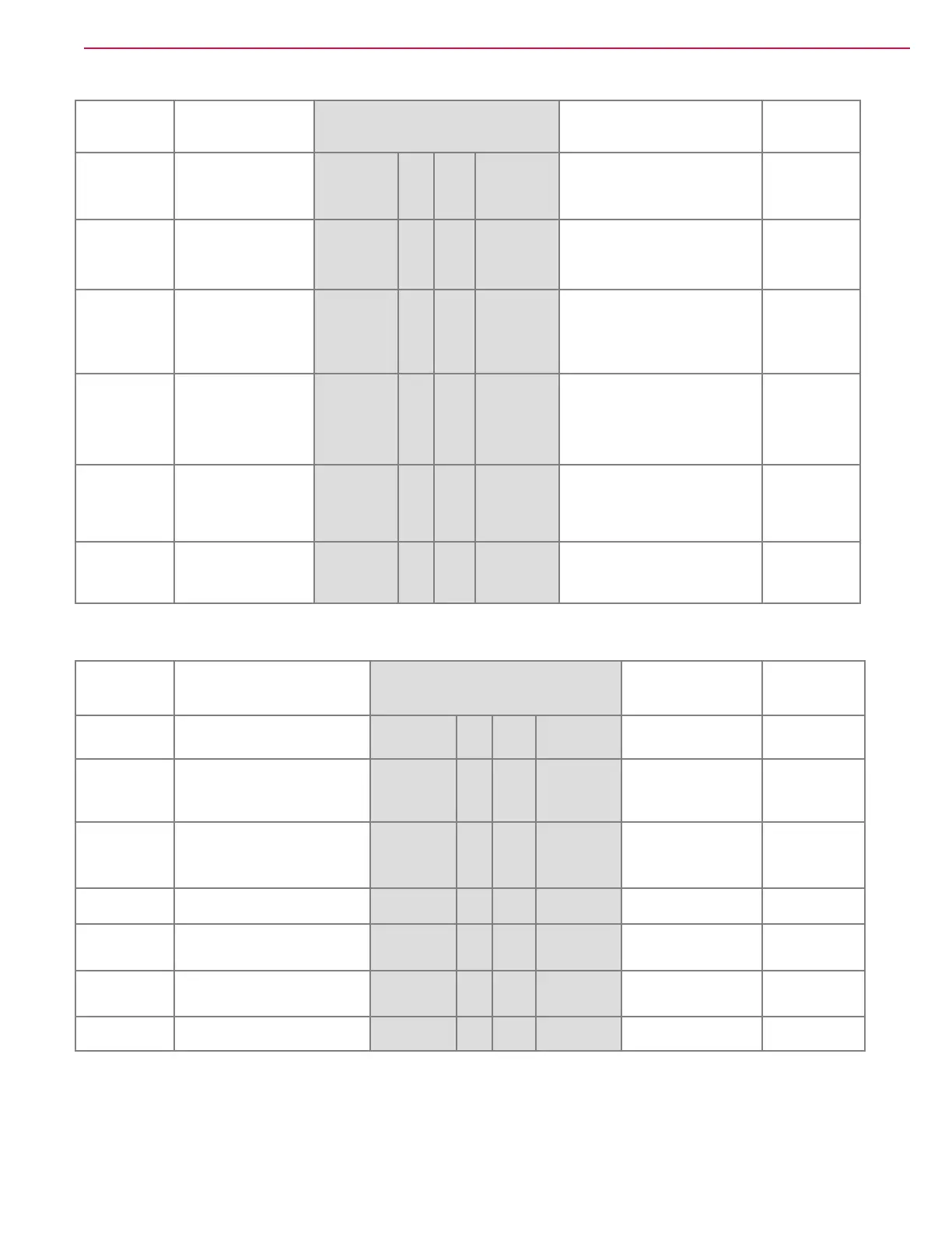
Backprobe J2 - Speed Control outputs, ST deck and squeegee lever position, and sense wires, J2 connected at control board:
Referenced to Measure J2 Measure Referenced to
B- n/a YEL 6 12 BLK/YEL
ST squeegee lever switch S6
Closed sq down 0V
Open sq up 5V
B-
B- n/a VIO 5 11 ORN/RED
ST deck lever switch S5
Closed deck up 0V
Open deck down 5V
B-
B- n/a BLK/WHT 4 10
YEL/VIO
M7 & M8 sense
monitor brush heights for deck
actuator feedback
0-200 mV
B-
3 9
BRN/RED
M5 & M6 sense
monitor vac motors to determine
when tank is full
1-200 mV
B-
B+
Advenger / BR 755,
855 B- (ground) input
to board
+24V
Advenger /
BR 755, 855
BLK
2 8 BLK +24V B+
B+
B- (ground)
Input to board
+24V
BLK 1 7 BLK Advenger / BR 755, 855 +24V B+
Backprobe J3 - Output to Contactors, Solution Solenoid, Horn; Speed Control error status, EM Brake, reverse status, J3 connected at
control board :
Referenced to Measure J3 Measure Referenced to
B-
+24V ashed speed control status
error code
ORN/BLU 7 14 BRN Key switch +24V B-
B-
Speed control EM brake signal
+24V
(moving on / neutral off)
RED/WHT 6 13
WHT/RED
*
+24V for 2 sec to K2
then 18V pulsed voltage
B+
B-
Speed control reverse
direction +24V
(reverse off / forward on)
BLU/BLK 5 12
GRA/BLK
**
+24V for 2 sec to K1
then 18V pulsed voltage
B+
B- Seat switch +24V GRA/BLK 4 11
VIO/BLK
***
Pulsed +24V B+
3 10 ORN/RED -Output to horn +15V B-
B+
Advenger / BR 755, 855 Ground
+24V
BLK 2 9 GRN/BLK +Output to horn +15V B-
B-
Advenger / BR 755, 855 Power
+24V
BRN/YEL 1 8 BRN/YEL
* test point for brush motor contactor coil control error 63
** test point for vacuum contactor coil control error 64
*** test point for solution solenoid control error 62
 Loading...