Control System 41Service Manual – SC500
Function Board (EB1) Connectors (Continues)
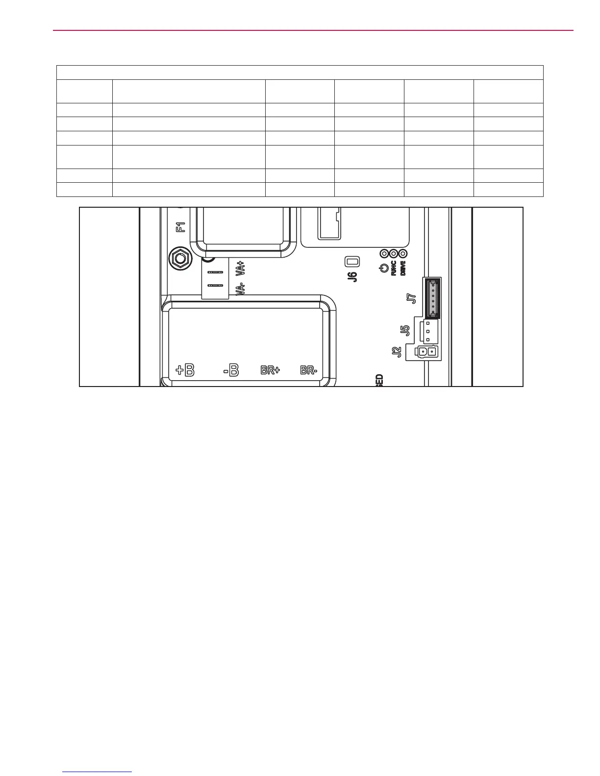
(Figure 28) J7: TYCO MODU II vertical 6-way
PIN Description Electronic board
in/out
V ref. I max. Connected to
1 +24V power supply out 24V <1A TRK.RD
2 +5V power supply out 5V <1A -
3 iButton input (CAN H channel) In (Out) 0V (0-5V) <1A TRK.YE
4 Ext. operating time counter enable (CAN
L channel)
(In) Out 0V (0-24V) <1A TRK.WH
5 Power supply - out 0V <1A TRK.BU
6 Machine on signal out 24V <1A TRK.BN
Figure 28

 Loading...


