Control System 50Service Manual – SC500
Shop Measurements - Function Board (EB1) (continues)
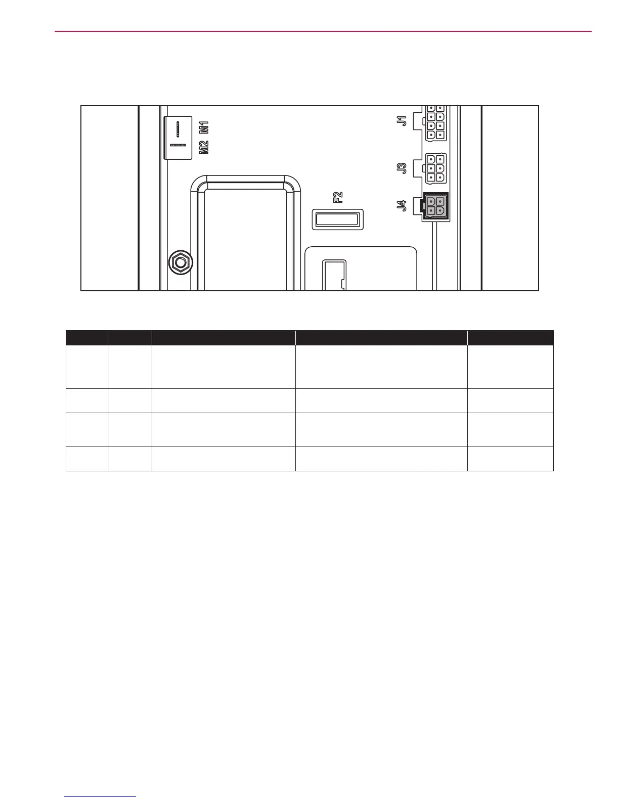
J4
Figure 40
PIN Color Circuit Description Measured Comments
1 White Enabling from battery charger 24.8v Not Charging May see residual
voltage back-feeding
from the main board
here when charging.
2 Yellow Power supply from battery charger 0.136v Not charging
26.1v Charging
3 Brown Battery charger enabling power
supply
24.8v key on or off Constant power
whether charging or
not. Key on or off.
4 Green Battery charger data communication 4.98v when charger is rst plugged in. Then
dropped to 4.6

 Loading...


