Home
Nilfisk-Advance
Floor Machine
SC500
Nilfisk-Advance SC500 Service Manual
5
of 1
of 1 rating
130 pages
Give review
Manual
Specs
To Next Page
To Next Page
To Previous Page
To Previous Page
Loading...
Control System
51
Service Manual – SC500
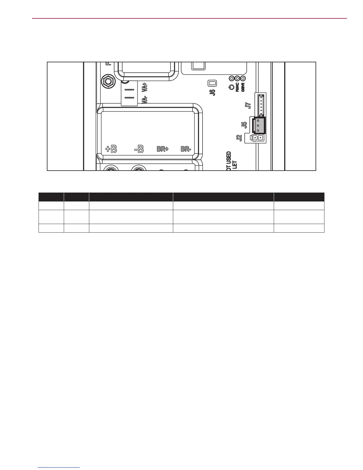
Shop Measurements - Function Board (EB1) (continues)
J5
Figure 41
PIN
Color
Circuit Description
Measured
Comments
1
Brown
Power supply for water level sensor +
24.7v
Key on
2
Black
W
ater level sensor return
4.98
0.03v
T
ank < ½ full
T
ank > ½ full
3
Blue
Power supply for water level sensor -
0.001
51
53
Table of Contents
Default Chapter
2
Table of Contents
2
General Information
5
Machine General Description
5
Service Manual Purpose and Field of Application
5
Other Reference Manuals
5
Conventions
6
Service and Spare Parts
6
Serial Number Label
6
Safety
7
Visible Symbols on the Machine
7
Symbols
7
General Instructions
8
Machine Lifting
10
Machine Transportation
10
Machine Nomenclature (Know Your Machine)
11
Control Panel (Disc Deck)
13
Service and Diagnostic Equipment
14
Technical Data
15
Dimensions
16
Nilfisk SC500 Disc
16
Advance SC500 REV
17
Maintenance
18
Scheduled Maintenance Table
18
Chassis System
19
Chassis (Main Parts)
19
Control System
20
Functional Description
20
Wiring Diagram
20
Component Locations
21
Maintenance and Adjustments
22
Function Board (EB1) Alarm Codes
22
Black-Box: Recording of Alarms, Parameters (See Pages 29-30), Partial Operating Time Counter
27
Display, Main Screen
27
Display, Alarms Log Screen
28
Display, Machine Settings Screen
29
System for Flow Rate Regulation as Function of Speed
31
Display, Operating Time Counter Screen
32
Removal and Installation
33
Function Board (EB1) Removal/Replacement
33
Display Board (EB2) and Dashboard Instrument Board (EB3) Removal/Replacement
35
Specifications
37
Function Board (EB1) Connectors
37
Display Board (EB2) Connectors
43
Shop Measurements
45
Shop Measurements - Function Board (EB1)
45
Shop Measurements - Display Board (EB2)
55
Electrical System
59
Functional Description
59
Wiring Diagram
59
Component Locations
60
Maintenance and Adjustments
61
Setting the Installed Battery Type
61
Battery Installation
62
Battery Charging
62
Battery Charge State Display
64
Checking/Replacing Fuses
64
Troubleshooting
65
Specifications
66
General Wiring Diagram
67
Recovery System
68
Functional Description
68
Wiring Diagram
68
Component Locations
69
Recovery Tank Cleaning
70
Troubleshooting
71
Removal and Installation
72
Vacuum Motor Current Draw Test
72
Vacuum Motor Unit Disassembly/Assembly
73
Container and Vacuum Motor Disassembly/Assembly
74
Specifications
77
Scrub System, Disc
78
Functional Description
78
Brush Release System
78
Wiring Diagram
78
Brush Deck Actuator System
79
Component Locations
80
Brush Installation/Removal
82
Troubleshooting
83
Removal and Installation
84
Brush Motor Current Draw Test
84
Brush Deck Disassembly/Assembly
85
Checking/Replacing Brush Motor Carbon Brushes
87
Brush Motor Disassembly/Assembly
88
Brush Deck Actuator Disassembly/Assembly
89
Specifications
90
Scrub System, REV
91
Functional Description
91
Wiring Diagram
91
Brush Deck Actuator System
92
Component Locations
93
Maintenance and Adjustments
95
Brush or Pad Installation/Removal
95
Troubleshooting
96
Removal and Installation
97
REV Motor Current Draw Test
97
REV Deck Disassembly/Assembly
98
Checking/Replacing REV Motor Carbon Brushes
100
REV Deck Actuator Disassembly/Assembly
103
Specifications
104
Solution System
105
Functional Description
105
Wiring Diagram
105
Component Locations
106
Maintenance and Adjustments
108
Cleaning the Detergent Solution Tank and Filter
108
Cleaning the Ecoflex Detergent Tank
109
Draining the Ecoflex System
110
Troubleshooting
111
Removal and Installation
113
Solenoid Valve Disassembly/Assembly
113
Detergent Pump Disassembly/Assembly
114
Water Level Sensor Operation
115
Checking the Water Level Sensor Operation
115
Water Level Sensor Disassembly/Assembly
116
Specifications
117
Squeegee System
118
Functional Description
118
Component Locations
119
Maintenance and Adjustments
120
Squeegee Cleaning
120
Checking/Replacing the Squeegee Blades
121
Troubleshooting
122
Removal and Installation
123
Disassembly/Assembly of the Gas Spring on the Squeegee Support
123
Specifications
124
Wheel System, Traction
125
Functional Description
125
Wiring Diagram
125
Component Locations
126
Troubleshooting
127
Maintenance and Adjustments
128
Speed Potentiometer Removal/Replacement
128
Drive System Gear Motor Current Draw Test
129
Specifications
130
Other manuals for Nilfisk-Advance SC500
Instructions For Use
29 pages
Operating Instructions
2 pages
Troubleshooting Guide
2 pages
How-To Guide
3 pages
5
Based on 1 rating
Ask a question
Give review
Questions and Answers:
Need help?
Do you have a question about the Nilfisk-Advance SC500 and is the answer not in the manual?
Ask a question
Nilfisk-Advance SC500 Specifications
General
Brand
Nilfisk-Advance
Model
SC500
Category
Floor Machine
Language
English
Related product manuals
Nilfisk-Advance SC500 9087352020
116 pages
Advance SC500 X20 B
188 pages
Nilfisk-Advance SC351
84 pages
Nilfisk-Advance SC8000
116 pages
Nilfisk-Advance SC1500
100 pages
Nilfisk-Advance SC6000
140 pages
Nilfisk-Advance SC900-28D
77 pages
Nilfisk-Advance SC401 Series
173 pages
SCRUBTEC 344 Series
173 pages
Nilfisk-Advance SW8000
8 pages
Nilfisk-Advance Sprite Plus 12
15 pages
56263501 Aquamatic Selectric
15 pages

 Loading...


