NIRStar 14.1 - User Manual
Page 43 of 124
6.2 Diagnostics
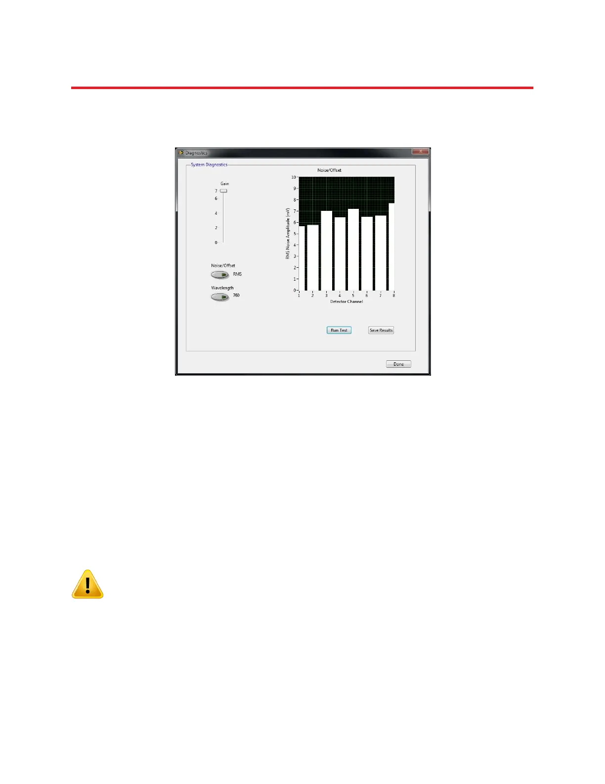
The diagnostics window is shown in Figure 27 below.
This feature allows users to test the dark noise performance of each detector, at each gain setting, for
both wavelengths.
The ‘dark noise’ characterizes a detector channel’s sensitivity by evaluating the amplitude and variance
of the detector reading if no input signal (i.e., incident light) is present. The residual signal variation is
caused by the fundamental noise of the light sensor and the electronics and is a measure of the optical
sensitivity of the device. Increased noise values can be indicative of faulty hardware (sensor or
subsequent electronics). The acceptable noise levels depend on the type of system used; for NIRScout
systems, the noise should stay well below 0.1 mV for Gains 0-5, and below 1.0 mV for Gain 6. For Gain 7,
less than 10 mV of noise is to be expected. Please see Section 16.1.4 for NIRSport considerations.
When performing a dark-noise test, it is CRITICAL that stray light be prevented from entering
the optical detector fibers or the fiber ports on the detector cards. Fiber tips and open
connectors must be optically well shielded from ambient light, by covering them with opaque
materials (e.g., heavy black cloth, black plastic foil, etc.).
Before running the dark noise test by clicking the OK button, ensure that the detector inputs are well
shielded from ambient light. The bar graph displays the noise or offset level for each detector, in units of
mV on the y-axis. The user can manually adjust the gain with the slider, in order to observe the gain-
factor dependence of the noise (here, a noise level is defined as the root-mean-square (RMS) value of a
sequence of detector readings).
Figure 27. Diagnostics window with dark noise test.