MS51
Nov. 28, 2019 Page 220 of 491 Rev 1.00
MS51 32K SERIES TECHNICAL REFERENCE MANUAL
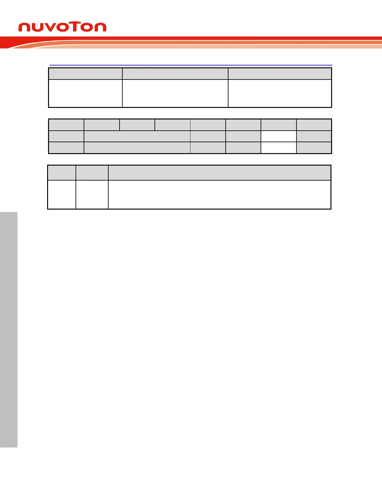
BODCON0 – Brown-out Detection Control 0
A3H, Page 0, TA protected
POR,CCCC XC0X b
BOD, UUUU XU1X b
Others,UUUU XUUX b
Brown-out reset flag
When the MCU is reset by brown-out event, this bit will be set via hardware. This flag is
recommended to be cleared via software.
External Reset and Hard Fault Reset 6.2.4.4
The external reset pin RST
is an input with a Schmitt trigger. An external reset is accomplished by
holding the RST
pin low for at least 24 system clock cycles to ensure detection of a valid hardware
reset signal. The reset circuitry then synchronously applies the internal reset signal. Thus, the reset is
a synchronous operation and requires the clock to be running to cause an external reset.
Once the device is in reset condition, it will remain as long as RST
pin is low. After the RST
high is
removed, the MCU will exit the reset state and begin code executing from address 0000H. If an
external reset applies while CPU is in Power-down mode, the way to trigger a hardware reset is
slightly different. Since the Power-down mode stops system clock, the reset signal will asynchronously
cause the system clock resuming. After the system clock is stable, MCU will enter the reset state.
There is a RSTPINF (AUXR0.6) flag, which indicates an external reset took place. After the external
reset, this bit will be set as 1 via hardware. RSTPINF will not change after any reset other than a
power-on reset or the external reset itself. This bit can be cleared via software.
Hard Fault reset will occur if CPU fetches instruction address over Flash size, HardF (AUXR0.5) flag
will be set via hardware. HardF will not change after any reset other than a power-on reset or the
external reset itself. This bit can be cleared via software. If MCU run in OCD debug mode and
OCDEN = 0, hard fault reset will be disabled. Only HardF flag be asserted.
 Loading...


