MS51
Nov. 28, 2019 Page 436 of 491 Rev 1.00
MS51 32K SERIES TECHNICAL REFERENCE MANUAL
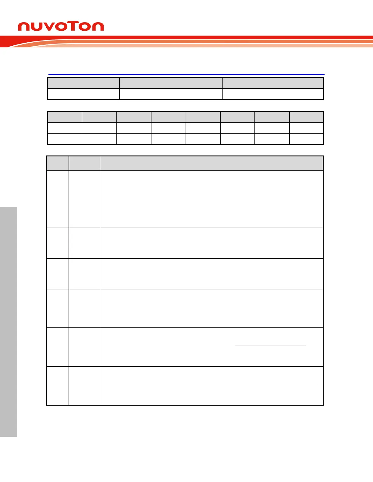
6.12.9 Control Register of SPI
SPCR – Serial Peripheral Control Register
Slave select output enable
This bit is used in combination with the DISMODF (SPSR.3) bit to determine the feature of SS
pin as
shown in Table 6.12-1 Slave Select Pin Configurations. This bit takes effect only under MSTR = 1 and
DISMODF = 1 condition.
0 = SS
functions as a general purpose I/O pin.
1 = SS
automatically goes low for each transmission when selecting external Slave device and goes
high during each idle state to de-select the Slave device.
SPI enable
0 = SPI function Disabled.
1 = SPI function Enabled.
LSB first enable
0 = The SPI data is transferred MSB first.
1 = The SPI data is transferred LSB first.
Master mode enable
This bit switches the SPI operating between Master and Slave modes.
0 = The SPI is configured as Slave mode.
1 = The SPI is configured as Master mode.
SPI clock polarity select
CPOL bit determines the idle state level of the SPI clock. See Figure 6.12-4 SPI Clock Formats.
0 = The SPI clock is low in idle state.
1 = The SPI clock is high in idle state.
SPI clock phase select
CPHA bit determines the data sampling edge of the SPI clock. See Figure 6.12-4 SPI Clock Formats.
0 = The data is sampled on the first edge of the SPI clock.
1 = The data is sampled on the second edge of the SPI clock.