MS51
Nov. 28, 2019 Page 447 of 491 Rev 1.00
MS51 32K SERIES TECHNICAL REFERENCE MANUAL
6.13.3 Control Registers of ADC
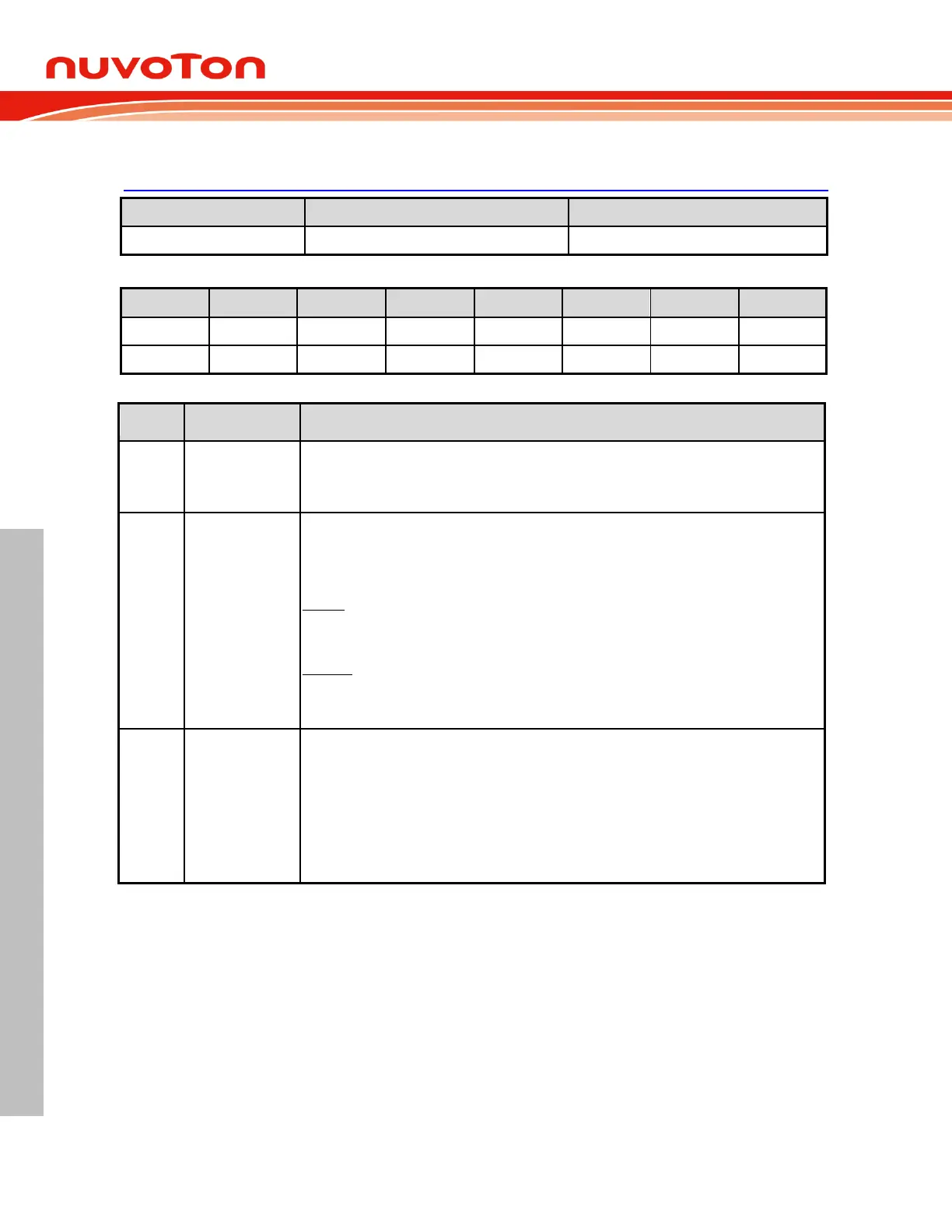
ADCCON0 – ADC Control 0 (Bit-addressable)
ADC flag
This flag is set when an A/D conversion is completed. The ADC result can be read. While this
flag is 1, ADC cannot start a new converting. This bit is cleared by software.
A/D converting software start trigger
Setting this bit 1 triggers an A/D conversion. This bit remains logic 1 during A/D converting
time and is automatically cleared via hardware right after conversion complete. The meaning
of writing and reading ADCS bit is different.
Writing:
0 = No effect.
1 = Start an A/D converting.
Reading:
0 = ADC is in idle state.
1 = ADC is busy in converting.
External trigger source select
When ADCEX (ADCCON1.1) is set, these bits select which pin output triggers ADC
conversion.
00 = PWM0.
01 = PWM2.
10 = PWM4
11 = STADC pin.