NV5128 Multi-Format Router • User’s Guide 39
3. Installation
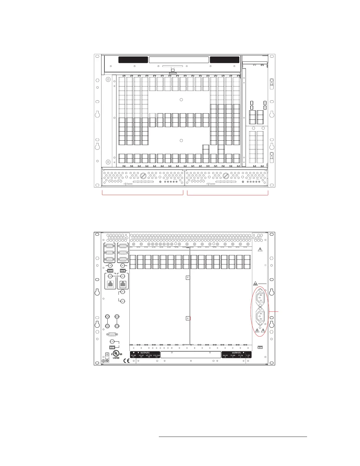
Connecting the Router to Power
Figure 3-1. PS6000 Power Supply Module Slot - No Cards Installed (Front View)
3 Facing the rear of the NV5128, connect one of the two power cords to ‘PS1’:
Figure 3-2. Power Connections - No Backplanes Installed (Rear View)
4 Connect the other end of the power supply cable to a source of AC power source (90-130/180-
250
VAC, 50/60 Hz).
5 Facing the rear of the NV5128, connect the remaining power cord to ‘PS2’, as shown in
Figure 3-2 on page 39.
PS6000 Primary Power Supply
Module Slot (PS1)
PS6000 Secondary Power Supply
Module Slot (PS2)
+
48V
1
PS6000
GND
2345
12345
POWER
+
48V
1
PS6000
GND
2345
12345
POWER
33-
48
7
1-
16
5
17-
32
6
49-
64
8
65-
80
9
81-
96
1
0
97-112
11
113-128
1
2
INP
U
TSOUTP
U
TS OUTP
U
TS
113-128
1
3
97-112
1
4
81-
96
1
5
65-
80
1
6
1-
16
1
17-
32
2
33-
48
3
49-
64
4
113-128
12
49-64
8
33-48
7
17-32
6
1-16
5
97-112
11
81-96
10
65-80
9
INPUTS
CTRL 1
CTRL 2
DIAG
CTRL 1
CTRL 2
DIAG
VIDEO
REF 1
VIDEO
REF 2
ALARMS
TIMECODE
AES
REF
1
NVISION
AUX BUS
LOOP
THRU
(2)
10/100 BT
10/100 BT
CONTROL NO. 9K50
PROFESSIONAL
VIDEO/AUDIO
AES
REF
2
PRI CTRL
SEC CTRL
PRI CTRL
SEC CTRL
10 B 210 B 2
LOOPTHRU
LOOP
THRU
THIS EQUIPMENT HAS
MORETHAN ONE
POWER SUPPLYCO RD.
TO REDUCETHE RISK
OF ELECTRIC SHOCK,
DISCONNECT 2 POWER
SUPPLY CORDS BEFORE
SERVICING.
CAUTION
PLEASE READ
INSTRUCTION MANUAL
BEFORECONNECTING
EQUIPMENTTO THE MAINS
FUSESLOCATED ON
POWER SUPPLIES
T 8.0A 250V
FOR 90-130V
~
T 6.3A 250V
FOR 180-250
~
PS 1
LEFT
PS 2
RIGHT
PS ALARMS
90-130/180-250V~
7.5A/3.75A
50/60Hz
660 WATTS MAX
E146905
1 AND 2
12COM
NORMALLY
CLOSED
Power
Connections