XYAA6336 Service Manual 1-9
1.6 LAYOUT OF THE DRAWER AND DISPLAY CONNECTORS
By means of the drawer and display option it is possible to drive a client drawer and display. Refer to Chapter 8
for instructions on how to install the related card.
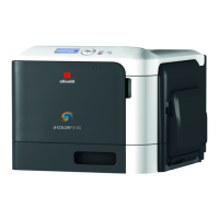
• Drawer Connector
Solenoid resistance 24 ohm min
Output voltage 24 volts
Current 1 amp Max
Printer side connector Molex 52065-6615 or equivalent
1 Frame GND
2 Drawer kick-out drive signal 1
3 Drawer open/close signal
4 + 24 V
5 Drawer kick-out drive signal 2
6 Signal GND
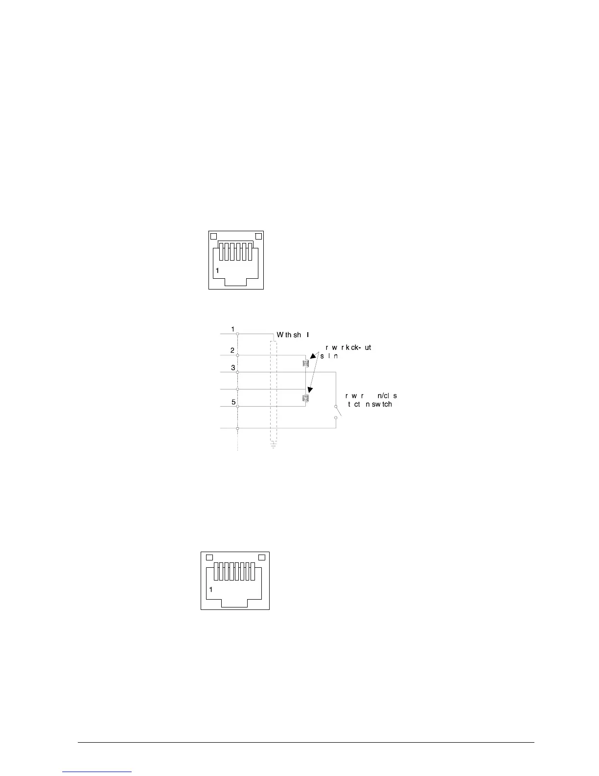
• Display Connector
By configuring the printer in the EPSON - TMU emulation it is possible to connect the EPSON DM D203-011
display.
1 Safety ground
2 Transmit data to print
3 Receive data from printer
4 Indicates whether the printers can receive data or not
5 Indicates whether the display can receive data or not
6 Signal ground
7 Power supply terminal
8 Power supply retrace line