XYAA6336 Service Manual 5-13
1
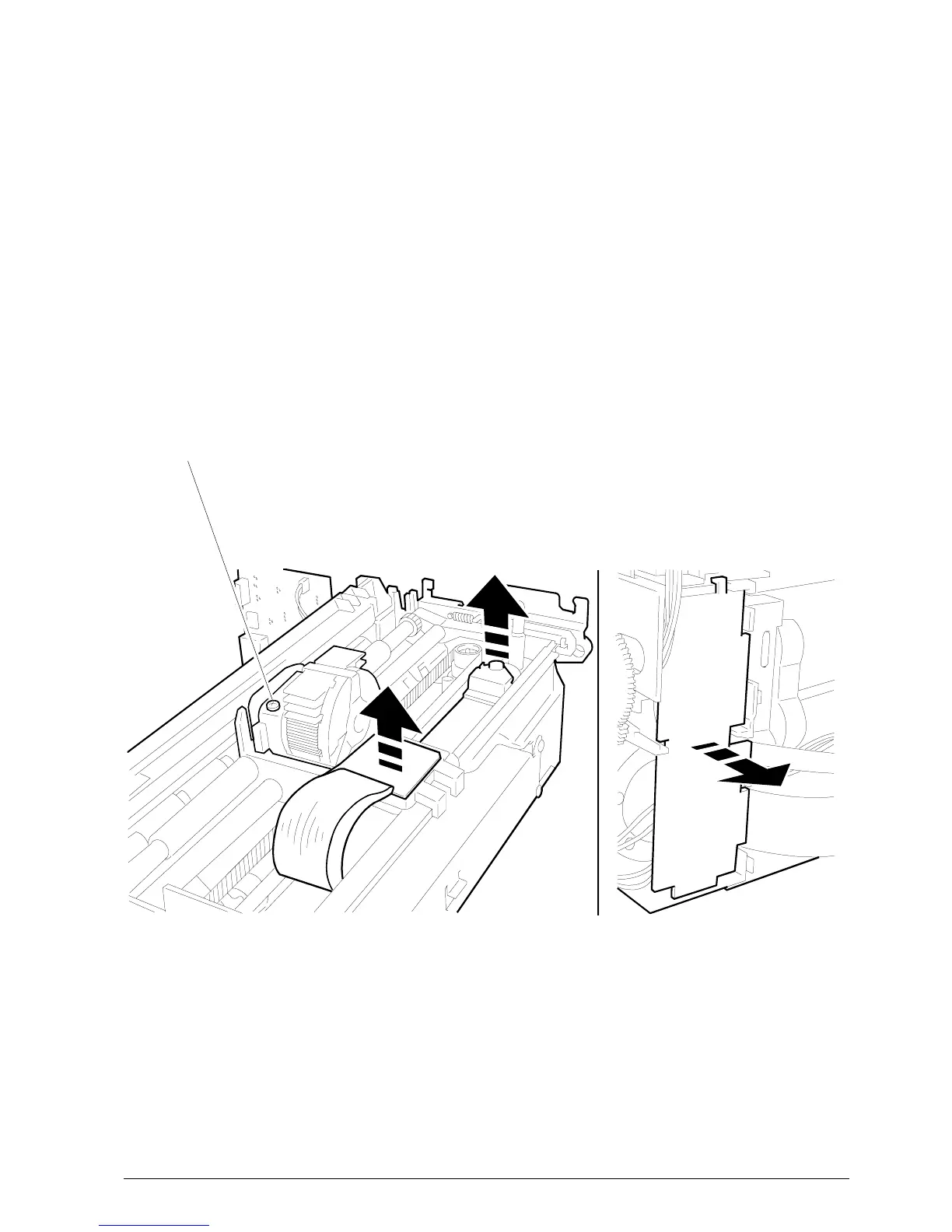
Figure 5-13 Figure 5-14
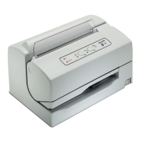
5.6 REMOVING THE PRINT HEAD
• Remove the case (Section 5-2).
• Remove screw 1.
• Remove the two boards to which the power supply
flat cable is connected as shown in Figure 5-13.
• Proceed as explained in Section 5.3 to access the
electronic board and therefore disconnect the flat
cable from connector J7 on this board.
• To completely extract the print head and related
flat cable remove the board shown in Figure 5-14;
gently bend this board so that it can be removed.
• To reassemble follow the disassembly procedure
in reverse order.
Note: After replacing the head readjust the parallelism
and the distance between the print head and
platen (Section 6.2)