XYAA6336 Service Manual 5-11
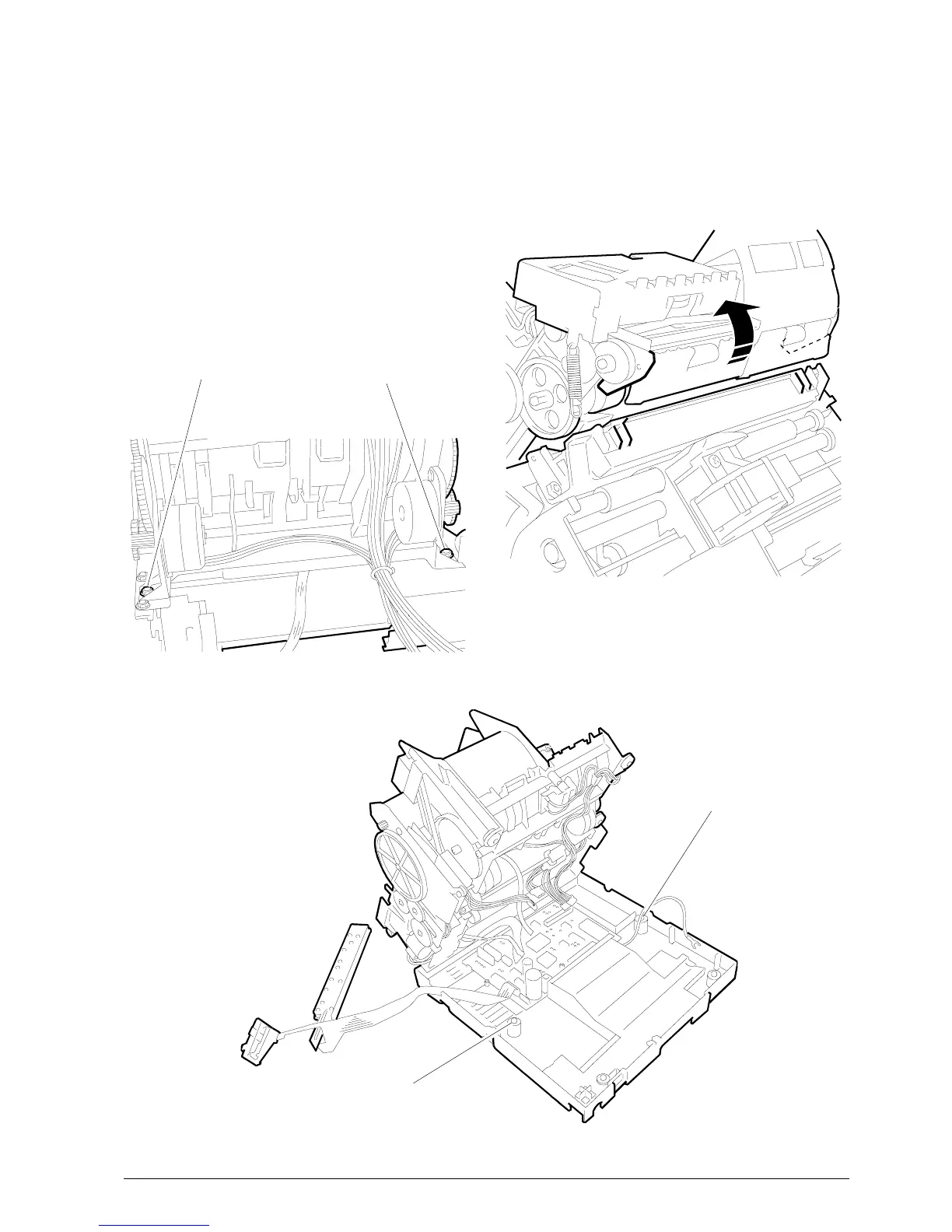
5.5 REMOVING THE PRINT ASSEMBLY
• Remove the case (Section 5.2).
• Remove screws 1 and 2 shown in the figure so as
to be able to lift the machine from the base
(Fig. 5.9).
• Disconnect the yellow ground cables of the print
and cutter assemblies.
• Disconnect all the connectors from the electronic
board and separate the machine from the base.
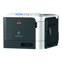
• Remove screws 3 and 4 (Fig. 5.8). Separate the
print unit from the paper feed unit by appropriately
rotating them (Fig. 5.7).
• To reassemble follow the disassmbly procedures
in reverse order giving special consideration to the
hooking points shown in the figure (Fig. 5.7).
2
1
4
3
Figure 5-8
Figure 5-7
Figure 5-9