6-2Service ManualXYAA6336
6.2 ADJUSTING THE PARALLELISM
AND PRINT HEAD-PLATEN
DISTANCE
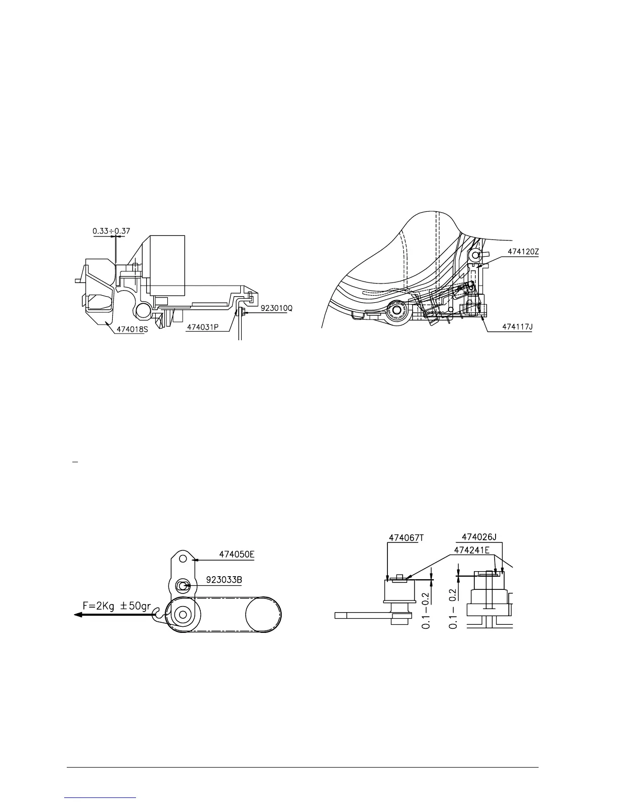
By means of friction screws 923010Q, higher or lower
the plate code 474031P until obtaining the parallelism
between the print head and platen. Then check, using
a probe, for a clearance of 0.33 - 0.37 mm between
the needle profile and platen code 474018S (Fig 6-2).
6.4 ADJUSTING THE OUT OF
JOURNAL AND RECEIPT PAPER
MICROSWITCH SUPPORT
PR4: Position the microswitch support half way along
the total run using the tab regulator code 474120Z
(Fig. 6-4) or according to the client's requirements.
PR4 SR: Position the microswitch support as follows:
for a 139.7 mm wide roll, all the way forwards towards
the operator; for 114.3 and 82.6 wide rolls, half way
along the total run; for the 72.6 mm wide roll, all the
way backwards from the operator.
Figure 6-2
6.3 ADJUSTING THE TENSION OF THE
CARRIAGE TRANSPORT BELT
Pulling the end pulley support bracket with a
dynamometer in the direction of the arrow, tighten the
transport belt until reaching a value of 2 Kg
+ 50 gr. Using the screw code 923033B, block the
bracket code 474050E on the structure code 474015P
(Fig. 6-3).
Figure 6-3
Figure 6-4
Figure 6-5
6.5 MOUNTING THE SNAP RINGS ON
THE CARRIAGE TRANSPORT
ASSEMBLY
During the assembly of codes 474067T, 474059B and
474026J, snap ring code 474241E must have a
clearance of 0.1 - 0.2 (Fig. 6-5). Clearance is obtained
by inserting a probe between the snap ring and the
stop point.