7-3
7 High-speed Counters
CJ2M CPU Unit Pulse I/O Module User’s Manual
7-1 Overview
7
7-1-2 Application Procedure
7-1-2 Application Procedure
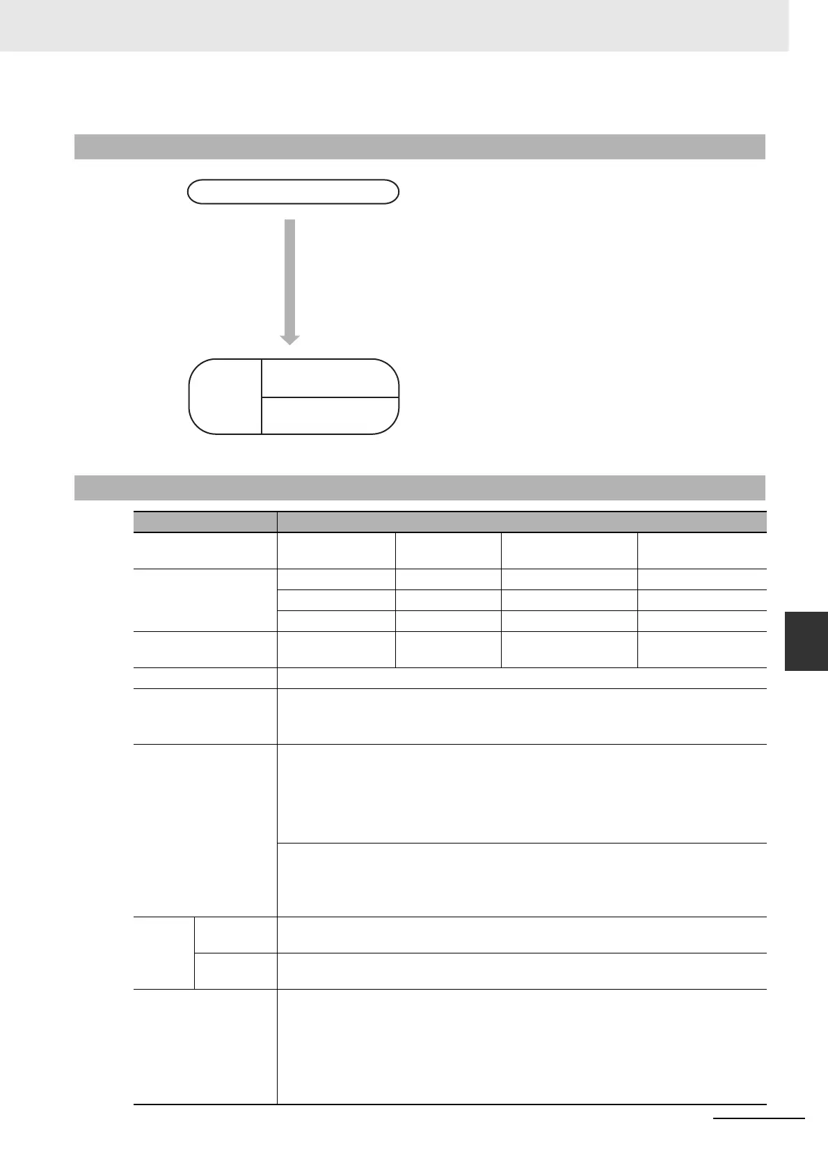
1
• Enable the required high-speed counters.
• Select the required input pulse frequency from the High-
speed Counter Detailed Settings Dialog Box that is
accessed from the I/O Module Tab Page of the PLC Setup
using the CX-Programmer. Set the counting mode, reset
method, pulse input mode, and other parameters.
• Input terminals IN02, IN03, IN06 to IN09, IN12, IN13, and
IN16 to IN19 can be used for high-speed counters. High-
speed counters 0 to 3 correspond to these.
2
• Read the PV from the Auxiliary Area or by executing a
PRV(881) instruction.
• Execute PRV(881).
7-1-3 Specifications
Item Description
Pulse input method
(counting mode)
Incremental pulse
inputs
Differential
phase input (4×)
Up/down inputs Pulse + direction
inputs
Input signals Increment pulse Phase A Up pulse Pulse
--- Phase B Down pulse Direction
--- Phase Z Reset Reset
Frequency and number
of high-speed counters
100 kHz, 2 inputs ×
2 I/O Modules
50 kHz, 2 inputs
× 2 I/O Modules
100 kHz, 2 inputs
× 2 I/O Modules
100 kHz, 2 inputs
× 2 I/O Modules
Counting mode Linear mode or ring mode
Count value Linear mode: 8000 0000 to 7FFF FFFF hex
0000 0000 to FFFF FFFF hex (for increment pulse)
Ring mode: 0000 0000 to Max. ring value
High-speed counter PV
storage locations
High-speed counter 0: A271 (upper 4 digits) and A270 (lower 4 digits)
High-speed counter 1: A273 (upper 4 digits) and A272 (lower 4 digits)
High-speed counter 2: A317 (upper 4 digits) and A316 (lower 4 digits)
High-speed counter 3: A319 (upper 4 digits) and A318 (lower 4 digits)
Refreshed during overseeing processing. Use PRV(881) to read the most recent PVs.
Data format: 8 digit hexadecimal
• Linear mode: 8000 0000 to 7FFF FFFF hex
0000 0000 to FFFF FFFF hex (for increment pulse)
• Ring mode: 0000 0000 to Max. ring value
Control
method
Target value
comparison
Up to 48 target values and corresponding interrupt task numbers can be registered.
Range Com-
parison
Up to 8 or up to 32 ranges can be registered, with a separate upper limit, lower limit,
and interrupt task number for each range.
Counter reset method • Phase-Z + Software reset
The counter is reset when the phase-Z input goes ON while the Reset Bit (A531.00 to
A531.03) is ON.
• Software reset
The counter is reset when the Reset Bit (A531.00 to A531.03) is turned ON.
Operation can be set to stop or continue the comparison operation when the high-
speed counter is reset.
PLC Setup
Reading counter PVs
Reading counter
frequencies
Create
ladder
program.
 Loading...


