4-9
4 Normal I/O
CJ2M CPU Unit Pulse I/O Module User’s Manual
4-3 Wiring
4
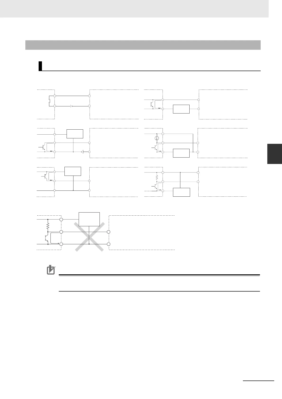
4-3-2 Wiring Examples
Precautions for Correct UsePrecautions for Correct Use
The Pulse I/O Module inputs have polarity. The inputs will not go ON if the wiring is reversed.
Always double-check the wiring before turning ON the power.
4-3-2 Wiring Examples
Examples for DC Input Devices
Note: Do not use the following wiring with voltage-output devices.
+
+
IN (24 VDC)
IN (0 V)
IN (0 V)
IN (24 VDC)
IN (0 V)
IN (24 VDC)
+
0 V
IN (0 V)
IN (24 VDC)
+
0 V
+
0 V
IN (24 VDC)
IN (0 V)
+
0 V
IN (24 VDC)
IN (0 V)
Output
Output
Output
Output
• Device with Contact Outputs
• Device with NPN Open Collector Output
• Device with PNP Current Output
• Two-wire DC Sensor
• Device with NPN Current Output
• Device with Voltage Output
Input in Pulse I/O
Module I/O
Input in Pulse I/O
Module I/O
Rated
current
circuit
Input in Pulse I/O
Module I/O
Input in Pulse I/O
Module I/O
Input in Pulse I/O
Module I/O
Input in Pulse I/O
Module I/O
Sensor
Power Supply
+
0 V
IN (24 VDC)
IN (0 V)
Output
Sensor
power
supply
Input in Pulse I/O
Module I/O
Sensor
power supply
Sensor
power supply
Sensor
Power Supply
Sensor
power supply
 Loading...


