8 Pulse Outputs
8-36
CJ2M CPU Unit Pulse I/O Module User’s Manual
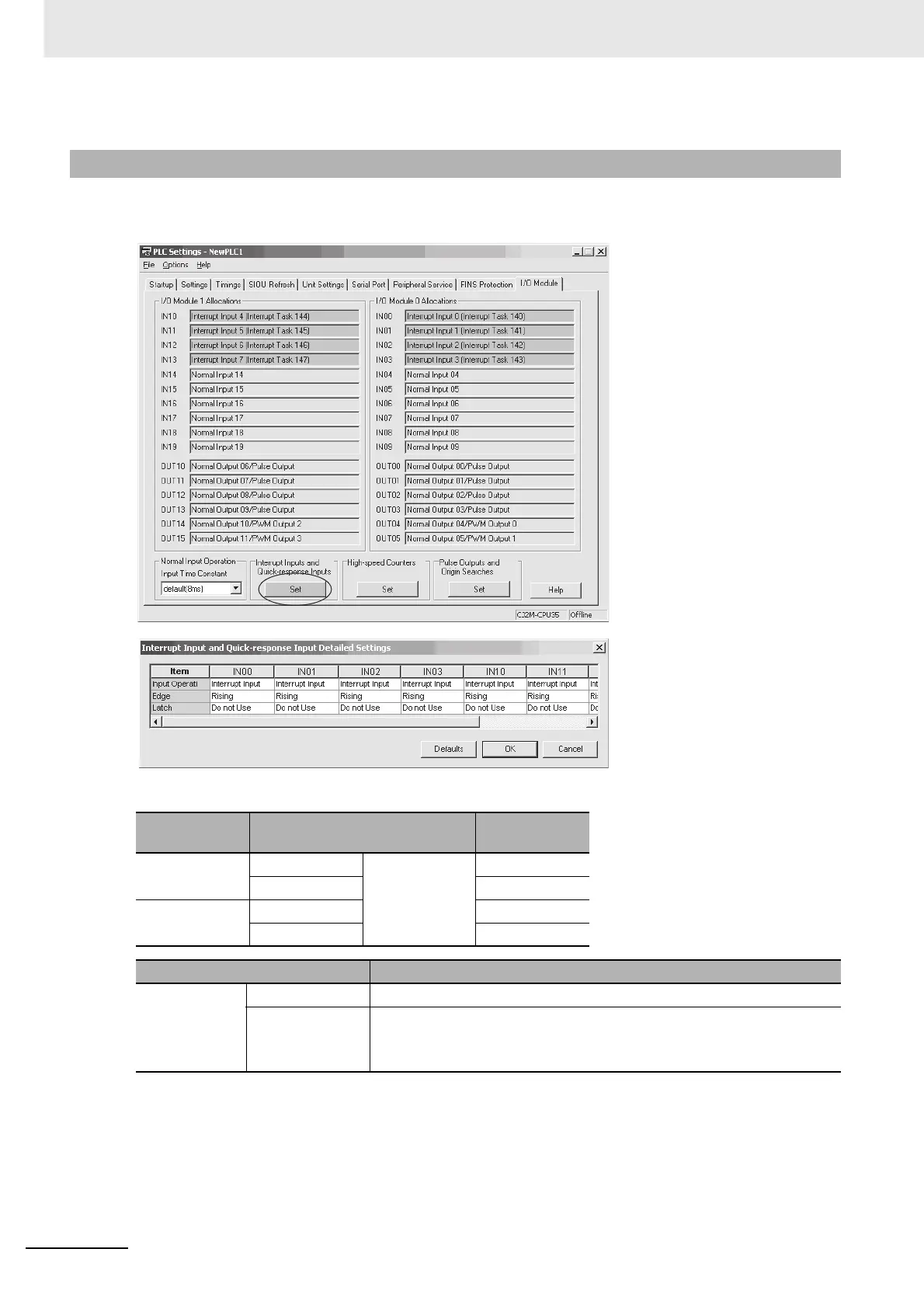
Click the I/O Module Tab in the PLC Setup. Select Interrupt Input in the Interrupt Input and Quick-
response Input Detailed Settings Dialog Box.
Interrupt Input and Quick-response Input Detailed Settings
8-4-3 PLC Setup
Pulse I/O Mod-
ule No.
Input Operation setting
Correspond-
ing bit address
0 (on the right) IN00 Select Interrupt
for any of the
following: IN00,
IN01, IN10, or
IN11.
2960.00
IN01 2960.01
1 (on the left) IN10 2962.00
IN11 2962.01
Item Setting
Interrupt inputs
0, 1, 4, and 5
Input Operation Select Interrupt.
Edge Select one of the following.
• Rising Edge (ON transition)
• Falling Edge (OFF transition)
 Loading...


