4 Normal I/O
4-4
CJ2M CPU Unit Pulse I/O Module User’s Manual
1 (on the
left)
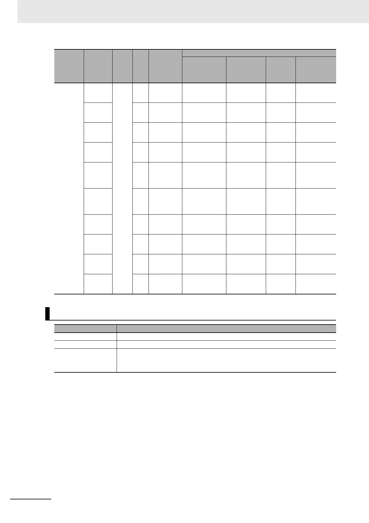
IN10 CIO
2962
00 Normal input
10
--- Quick-response
input 4
Interrupt
input 4
Pulse output 2
origin input sig-
nal
IN11 01 Normal input
11
--- Quick-response
input 5
Interrupt
input 5
Pulse output 2
origin proximity
input signal
IN12 02 Normal input
12
Counter 3 phase
Z or reset input
Quick-response
input 6
Interrupt
input 6
Pulse output 3
origin input sig-
nal
IN13 03 Normal input
13
Counter 2 phase
Z or reset
Quick-response
input 7
Interrupt
input 7
Pulse output 3
origin proximity
input signal
IN14 04 Normal input
14
--- --- --- Pulse output 2
positioning
completed sig-
nal
IN15 05 Normal input
15
--- --- --- Pulse output 3
positioning
completed sig-
nal
IN16 06 Normal input
16
Counter 3 phase
A, increment, or
count input
--- --- ---
IN17 07 Normal input
17
Counter 3 phase
B, decrement, or
direction input
--- --- ---
IN18 08 Normal input
18
Counter 2 phase
A, increment, or
count input
--- --- ---
IN19 09 Normal input
19
Counter 2 phase
B, decrement, or
direction input
--- --- ---
Specifications
Item Specifications
Number of inputs 20 inputs
Allocated bit CIO 2960 and CIO 2962, bits 00 to 09
Input time constant
(ON/OFF response
time)
Default: 8 ms
The following settings can be made in the PLC Setup: 0 ms (no filter), 0.5 ms, 1 ms, 2
ms, 4 ms, 8 ms, 16 ms, or 32 ms.
Pulse I/O
Module
No.
Terminal
symbol
Word Bit Function
Other functions that cannot be used at the same time
High-speed
counter inputs
Quick-
response
inputs
Interrupt
inputs
Origin search
inputs for
pulse outputs
0 to 3
 Loading...


