3-7
3 I/O Specifications and Wiring for Pulse I/O Modules
CJ2M CPU Unit Pulse I/O Module User’s Manual
3-2 Wiring
3
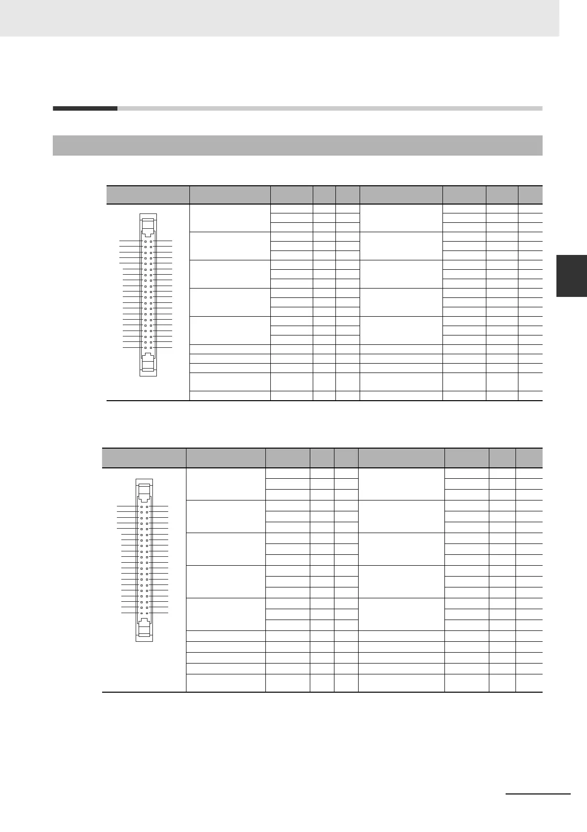
3-2-1 Connector Pin Allocations
3-2 Wiring
z Connector on Sinking-type I/O Module (CJ2M-MD211)
* Terminals numbers on the XW2D-@@G@ Connector-Terminal Block Conversion Unit.
z Sourcing-type I/O Module (CJ2M-MD212)
* Terminals numbers on the XW2D-@@G@ Connector-Terminal Block Conversion Unit.
3-2-1 Connector Pin Allocations
Pin layout Terminal symbol
Input sig-
nal type
Pin * Terminal symbol
Input sig-
nal type
Pin *
IN00/IN10 24 VDC 1 A1 IN01/IN11 24 VDC 2 B1
LD+ 3 A2 LD+ 4 B2
0 V/LD− 5A3 0 V/LD− 6B3
IN02/IN12 24 VDC 7 A4 IN03/IN13 24 VDC 8 B4
LD+ 9 A5 LD+ 10 B5
0 V/LD− 11 A6 0 V/LD− 12 B6
IN04/IN14 24 VDC 13 A7 IN05/IN15 24 VDC 14 B7
LD+ 15 A8 LD+ 16 B8
0 V/LD− 17 A9 0 V/LD− 18 B9
IN06/IN16 24 VDC 19 A10 IN07/IN17 24 VDC 20 B10
LD+ 21 A11 LD+ 22 B11
0 V/LD− 23 A12 0 V/LD− 24 B12
IN08/IN18 24 VDC 25 A13 IN09/IN19 24 VDC 26 B13
LD+ 27 A14 LD+ 28 B14
0 V/LD− 29 A15 0 V/LD− 30 B15
OUT00/OUT10 --- 31 A16 OUT01/OUT11 --- 32 B16
OUT02/OUT12 --- 33 A17 OUT03/OUT13 --- 34 B17
OUT04/OUT14 --- 35 A18 OUT05/OUT15 --- 36 B18
Power supply input +V
for outputs
--- 37 A19 Power supply input +V
for outputs
--- 38 B19
COM --- 39 A20 COM --- 40 B20
Pin layout Terminal symbol
Input sig-
nal type
Pin * Terminal symbol
Input sig-
nal type
Pin *
IN00/IN10 24 VDC 1 A1 IN01/IN11 24 VDC 2 B1
LD+ 3 A2 LD+ 4 B2
0 V/LD− 5A3 0 V/LD− 6B3
IN02/IN12 24 VDC 7 A4 IN03/IN13 24 VDC 8 B4
LD+ 9 A5 LD+ 10 B5
0 V/LD− 11 A6 0 V/LD− 12 B6
IN04/IN14 24 VDC 13 A7 IN05/IN15 24 VDC 14 B7
LD+ 15 A8 LD+ 16 B8
0 V/LD− 17 A9 0 V/LD− 18 B9
IN06/IN16 24 VDC 19 A10 IN07/IN17 24 VDC 20 B10
LD+ 21 A11 LD+ 22 B11
0 V/LD− 23 A12 0 V/LD− 24 B12
IN08/IN18 24 VDC 25 A13 IN09/IN19 24 VDC 26 B13
LD+ 27 A14 LD+ 28 B14
0 V/LD− 29 A15 0 V/LD− 30 B15
OUT00/OUT10 --- 31 A16 OUT01/OUT11 --- 32 B16
OUT02/OUT12 --- 33 A17 OUT03/OUT13 --- 34 B17
OUT04/OUT14 --- 35 A18 OUT05/OUT15 --- 36 B18
COM --- 37 A19 COM --- 38 B19
Power supply input −V
for outputs
--- 39 A20 Power supply input −V
for outputs
--- 40 B20
1
3
5
7
9
11
13
15
17
19
21
23
25
27
29
31
33
35
37
39
2
4
6
8
10
12
14
16
18
20
22
24
26
28
30
32
34
36
38
40
1
3
5
7
9
11
13
15
17
19
21
23
25
27
29
31
33
35
37
39
2
4
6
8
10
12
14
16
18
20
22
24
26
28
30
32
34
36
38
40
 Loading...


