4 Normal I/O
4-10
CJ2M CPU Unit Pulse I/O Module User’s Manual
When using a two-wire sensor, check that the following conditions have been met. Failure to meet
these conditions may result in operating errors.
(1) Relation between voltage when the input is ON and the sensor residual voltage:
V
ON
≤ V
CC
− V
R
(2) Relation between current when the input is ON and the sensor control output (load
current):
I
OUT
(min.) ≤ I
ON
≤ I
OUT
(max.)
I
ON
= (V
CC
− V
R
− 1.5 [Internal residual voltage of input])/R
IN
When I
ON
is smaller than I
OUT
(min), connect a bleeder resistor R. The bleeder resistor con-
stant can be calculated as follows:
R ≤ (V
CC
− V
R
)/(I
OUT
(min.) − I
ON
)
Power W ≥ (V
CC
− V
R
)
2
/R × 4 (allowable margin)
(3) Relation between current when the input is OFF and the sensor leakage current:
I
OFF
≥ I
leak
Connect a bleeder resistor if I
leak
is greater than I
OFF
.
Use the following equation to calculate the bleeder resistance constant.
R ≤ R
IN
× V
OFF
/(I
leak
× R
IN
− V
OFF
)
Power W ≥ (V
CC
− V
R
)
2
/R × 4 (allowable margin)
(4) Precautions on Sensor Inrush Current
An incorrect input may occur due to sensor inrush current if a sensor is turned ON after the
PLC has started up to the point where inputs are possible.
Determine the time required for sensor operation to stabilize after the sensor is turned ON
and take appropriate measures, such as inserting into the program a timer delay after turn-
ing ON the sensor.
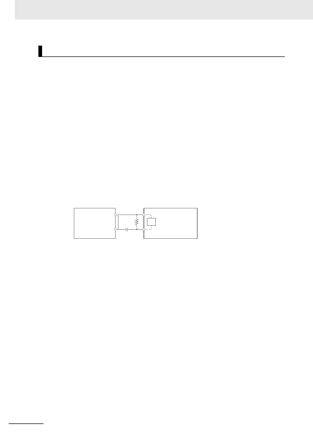
Precautions When Connecting a Two-wire DC Sensor
V
CC
: Power supply voltage V
R
: Sensor’s output residual voltage
V
ON
: Input’s ON voltage
V
OFF
: Input's OFF voltage
I
ON
: Input's ON current I
OUT
: Sensor’s control current (load current)
I
OFF
: Input's OFF current I
leak
: Sensor’s leakage current
R
IN
: Input's impedance R: Bleeder resistance
VCC
RVR RIN
2-wire sensor
Input in Pulse I/O
Module
 Loading...


