7-41
7 High-speed Counters
CJ2M CPU Unit Pulse I/O Module User’s Manual
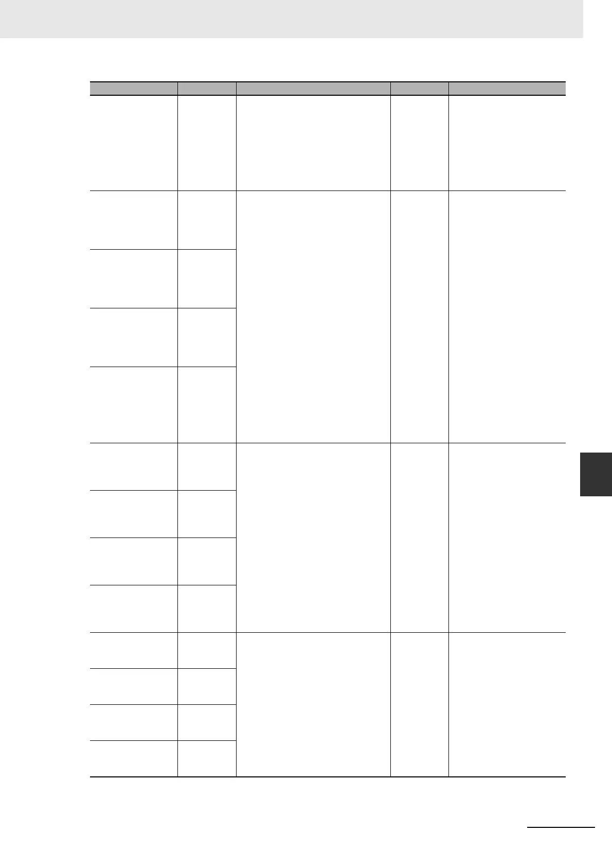
7-4 Related Auxiliary Area Words and Bits
7
High-speed
Counter 3 Count
Direction
A321.10 This flag indicates whether high-
speed counter 3 is currently being
incremented or decremented. The
counter PV for the current cycle is
compared with the PV in last cycle
to determine the result.
OFF: Decrementing
ON: Incrementing
Read • Setting used for high-
speed counter, valid
during counter opera-
tion.
High-speed
Counter 0 Range
Comparison Con-
dition 1 to 32 In-
range Flags
A10128 and
A10129
These flags indicate whether the
PV is within any of the 1 to 32
ranges when a high-speed counter
(0 to 3) is being operated in range-
comparison mode with upper and
lower limits.
The In-range Flags, however, will be
ON whenever the comparison value
is within the range regardless of the
whether the high-speed counter is
set to execute the interrupt task
when the range is entered or left.
OFF: Not in range
ON: In range
Bits 00 to 15 in the lower word cor-
respond to ranges 1 to 16. Bits 00
to 15 in the upper word correspond
to ranges 17 to 32.
Read • Cleared when power is
turned ON.
• Cleared when opera-
tion is started.
• Refreshed each cycle
(overseeing process-
ing).
• Refreshed when com-
parison is executed for 1
to 32 ranges.
• Refreshed when
PRV(881) instruction is
executed to read the
results of range compar-
ison.
• Refreshed when
INI(880) instruction is
executed to change PV
or ring counter maxi-
mum value.
•Reset
High-speed
Counter 1 Range
Comparison Con-
dition 1 to 32 In-
range Flags
A10130 and
A10131
High-speed
Counter 2 Range
Comparison Con-
dition 1 to 32 In-
range Flags
A10132 and
A10133
High-speed
Counter 3 Range
Comparison Con-
dition 1 to 32 In-
range Flags
A10134 and
A10135
High-speed
Counter 0 Ring
Counter Maximum
Value
A10136 and
A10137
Contain the ring counter maximum
values when high-speed counters 0
to 3 are used as ring counters.
These values are cleared to 0 if Lin-
ear Mode is used.
Lower four digits: A10136, A10138,
A10140, and A10142
Upper four digits: A10137, A10139,
A10141, and A10143
Read • Cleared when power is
turned ON.
• Cleared when opera-
tion starts.
• Refreshed when
INI(880) instruction is
executed to change ring
counter maximum
value.
High-speed
Counter 1 Ring
Counter Maximum
Value
A10138 and
A10139
High-speed
Counter 2 Ring
Counter Maximum
Value
A10140 and
A10141
High-speed
Counter 3 Ring
Counter Maximum
Value
A10142 and
A10143
High-speed
Counter 0 Reset
Bit
A531.00 When the reset method is set to a
phase-Z signal + software reset, the
corresponding high-speed counter's
PV will be reset if the phase-Z sig-
nal is received while this flag is ON.
When the reset method is set to a
software reset, the corresponding
high-speed counter's PV will be
reset in the cycle when this bit turns
ON.
Read/Write • Cleared when power is
turned ON.
High-speed
Counter 1 Reset
Bit
A531.01
High-speed
Counter 2 Reset
Bit
A531.02
High-speed
Counter 3 Reset
Bit
A531.03
Name Word/Bit Function Read/Write Refresh timing
 Loading...


