3-9
3 I/O Specifications and Wiring for Pulse I/O Modules
CJ2M CPU Unit Pulse I/O Module User’s Manual
3-2 Wiring
3
3-2-3 Wiring
Precautions for Safe Use
• Never apply a voltage that exceeds the input voltage of the I/O circuits or the maximum switch-
ing capacity of the output circuits.
• When the power supply has positive and negative terminals, always wire them correctly.
• Use reinforced insulation or double insulation for the DC power supplies used for I/O to comply
with the EC Low Voltage Directive.
• Always double-check the connector wiring before turning ON the power.
• Do not pull on the cable. Doing so will damage the cable.
• Do not bend the cable past its natural bending radius. Doing so will damage the cable.
• The connector pin allocation of the CJ1W-ID232/262 and OD233/263 connectors is not com-
patible. The Unit's internal circuits may be damaged if one of these connectors is connected.
• Do not connect a 24-VDC output device to a line driver input. Doing so may damage the inter-
nal circuits.
• Do not connect a line driver output device to the DC input. Doing so will not damage the inter-
nal circuits, but the input will not be recognized.
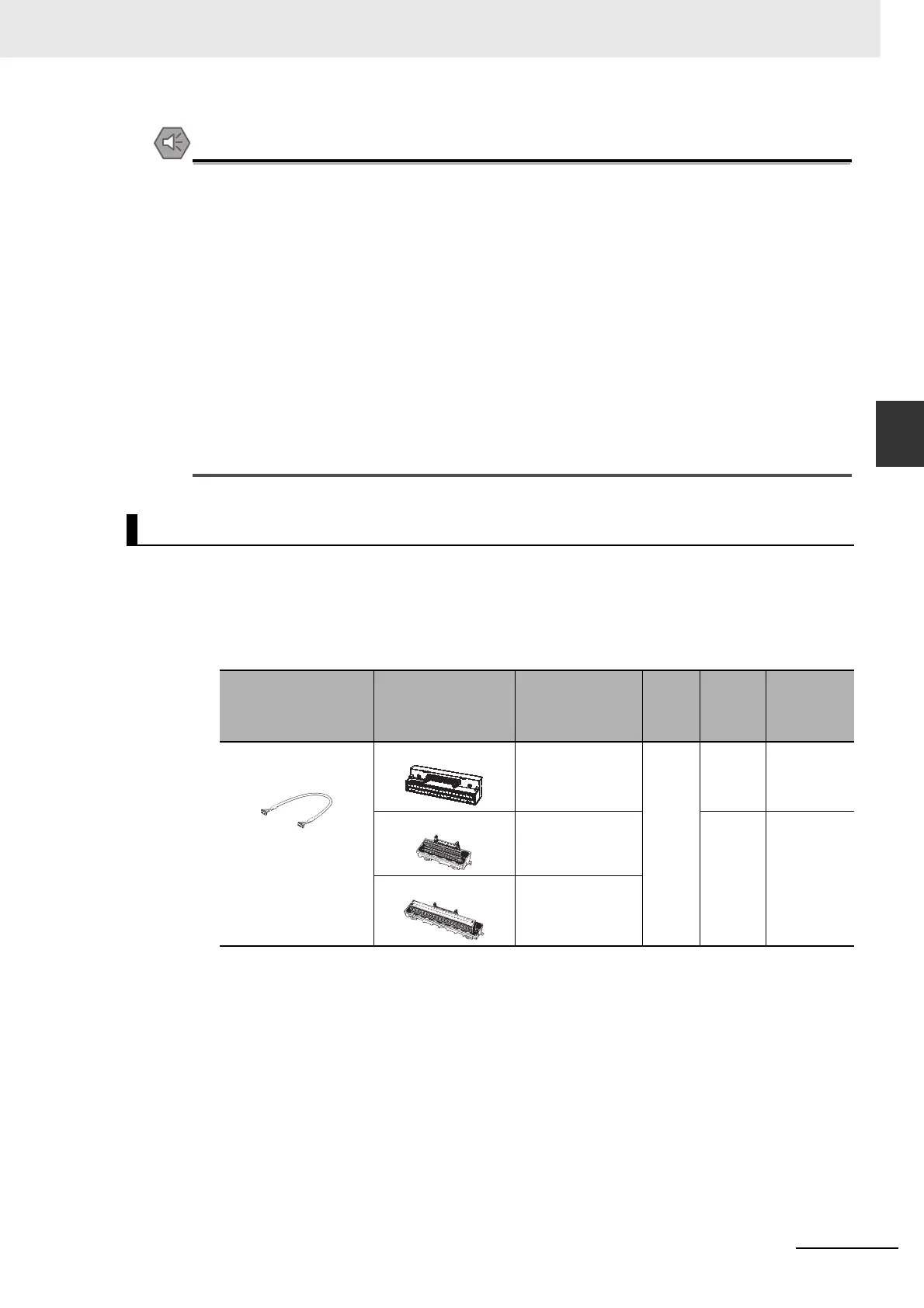
A special OMRON Connecting Cable with a connector is used to connect the Connector-Terminal
Block Conversion Unit.
z Cables for Connector-Terminal Block Conversion Units
Applicable Connector-Terminal Block Conversion Units
Using Connector-Terminal Block Conversion Units
Connecting Cable
Compatible Con-
nector-Terminal
Block Conversion
Unit
Type
Num-
ber of
pins
Size
Tempera-
ture (°C)
XW2Z-@@@K
@@@: 100: 1 m
150: 1.5 m
200: 2 m
300: 3 m
500: 5 m
XW2D-40G6 Slim type
(M3 screw termi-
nals)
40P Com-
pact
0 to 55
XW2B-40G4 Through cable
(M3 screw termi-
nals)
Stan-
dard
0 to 55
XW2B-40G5 Through cable
(M3.5 screw termi-
nals)
 Loading...


