189
Interrupt Functions Section 5-1
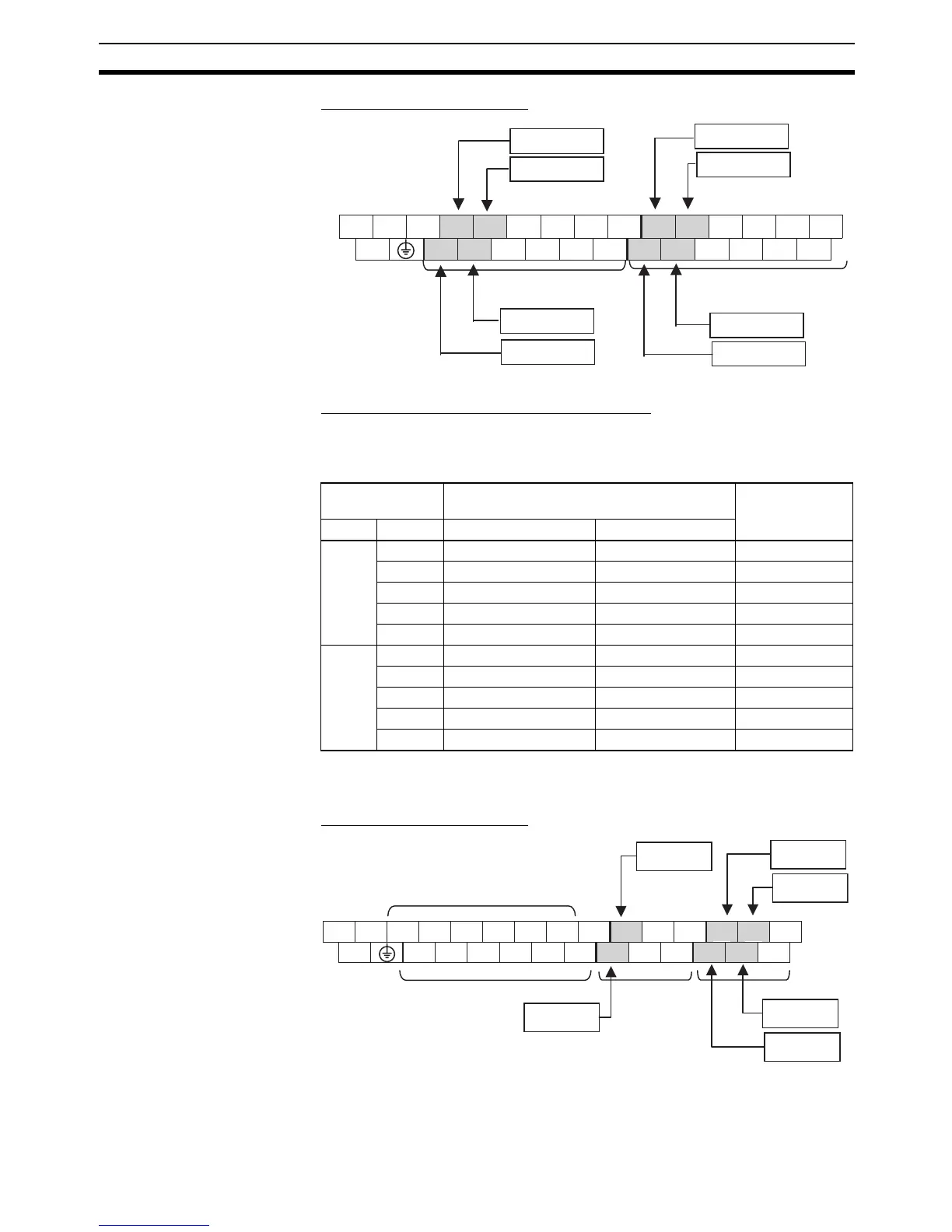
Input Terminal Arrangement
Setting the Input Functions in the PLC Setup
Normally, bits CIO 0.00 to CIO 0.03 and CIO 1.00 to CIO 1.03 are used as
normal inputs. When using these inputs for input interrupts, use the CX-Pro-
grammer to change the input’s setting in the PLC Setup.
Y CPU Units The 6 input bits CIO 0.00 to CIO 0.01 and CIO 1.00 to CIO 1.03 can be used
for input interrupts.
Input Terminal Arrangement
Input terminal
block
Input operation setting Task number
Word Bit Normal inputs Input interrupt
CIO 0 00 Normal input 0 Input interrupt 0 Interrupt task 140
01 Normal input 1 Input interrupt 1 Interrupt task 141
02 Normal input 2 Input interrupt 2 Interrupt task 142
03 Normal input 3 Input interrupt 3 Interrupt task 143
04 to 11 Normal inputs 4 to 11 --- ---
CIO 1 00 Normal input 12 Input interrupt 4 Interrupt task 144
01 Normal input 13 Input interrupt 5 Interrupt task 145
02 Normal input 14 Input interrupt 6 Interrupt task 146
03 Normal input 15 Input interrupt 7 Interrupt task 147
04 to 11 Normal inputs 16 to 23 --- ---
00 02 04 06 08 10 00 02 04 06 08 10
L1 L2/N COM 01 03 05 07 09 11 01 03 05 07 09 11
LG
Input interrupt 0
Input interrupt 2
Input interrupt 3
Input interrupt 1
Input interrupt 7
Input interrupt 5
Input interrupt 4
Input interrupt 6
Inputs (CIO 0) Inputs (CIO 1)
Upper Terminal Block
(Example: AC Power
Supply Modules)
NC
A0− B0− Z0− A1− B1− Z1− 00 04 10 00 02 04
+
−
A0+ B0+ Z0+ A1+ B1+ Z1+
COM
01 05 11 01 03 05
Upper Terminal Block
Input
interrupt 3
Inputs (CIO 0)
Inputs (CIO 1)
Input
interrupt 5
Input
interrupt 4
Input
interrupt 2
Input
interrupt 0
Input
interrupt 1
High-speed counter terminals
High-speed counter terminals