190
Interrupt Functions Section 5-1
Setting the Input Functions in the PLC Setup
Normally, bits CIO 0.00 to CIO 0.01 and CIO 1.00 to CIO 1.03 are used as
normal inputs. When using these inputs for input interrupts, use the CX-Pro-
grammer to change the input’s setting in the PLC Setup.
Procedure
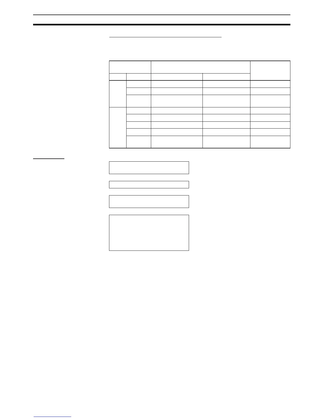
Input terminal
block
Input operation setting Task number
Word Bit Normal inputs Input interrupt
CIO 0 00 Normal input 0 Input interrupt 0 Interrupt task 140
01 Normal input 1 Input interrupt 1 Interrupt task 141
04, 05, 10
and 11
Normal inputs 2, 3, 4,
and 5
--- ---
CIO 1 00 Normal input 6 Input interrupt 2 Interrupt task 142
01 Normal input 7 Input interrupt 3 Interrupt task 143
02 Normal input 8 Input interrupt 4 Interrupt task 144
03 Normal input 9 Input interrupt 5 Interrupt task 145
04 and 05 Normal inputs 10 and
11
--- ---
Select the input interrupts.
• Determine the inputs to be used for input
interrupts and corresponding task numbers.
↓
Wire the inputs. • Wire the inputs.
↓
Set the PLC Setup.
• Use the CX-Programmer to select the inter-
rupt inputs in the PLC Setup.
↓
Write the ladder program.
• Write the programs for the corresponding
interrupt task numbers.
• Use MSKS(690) to specify up-differentiation
or down-differentiation.
• Use MSKS(690) to enable input interrupts (in
direct mode).