332
Analog I/O (XA CPU Units) Section 5-5
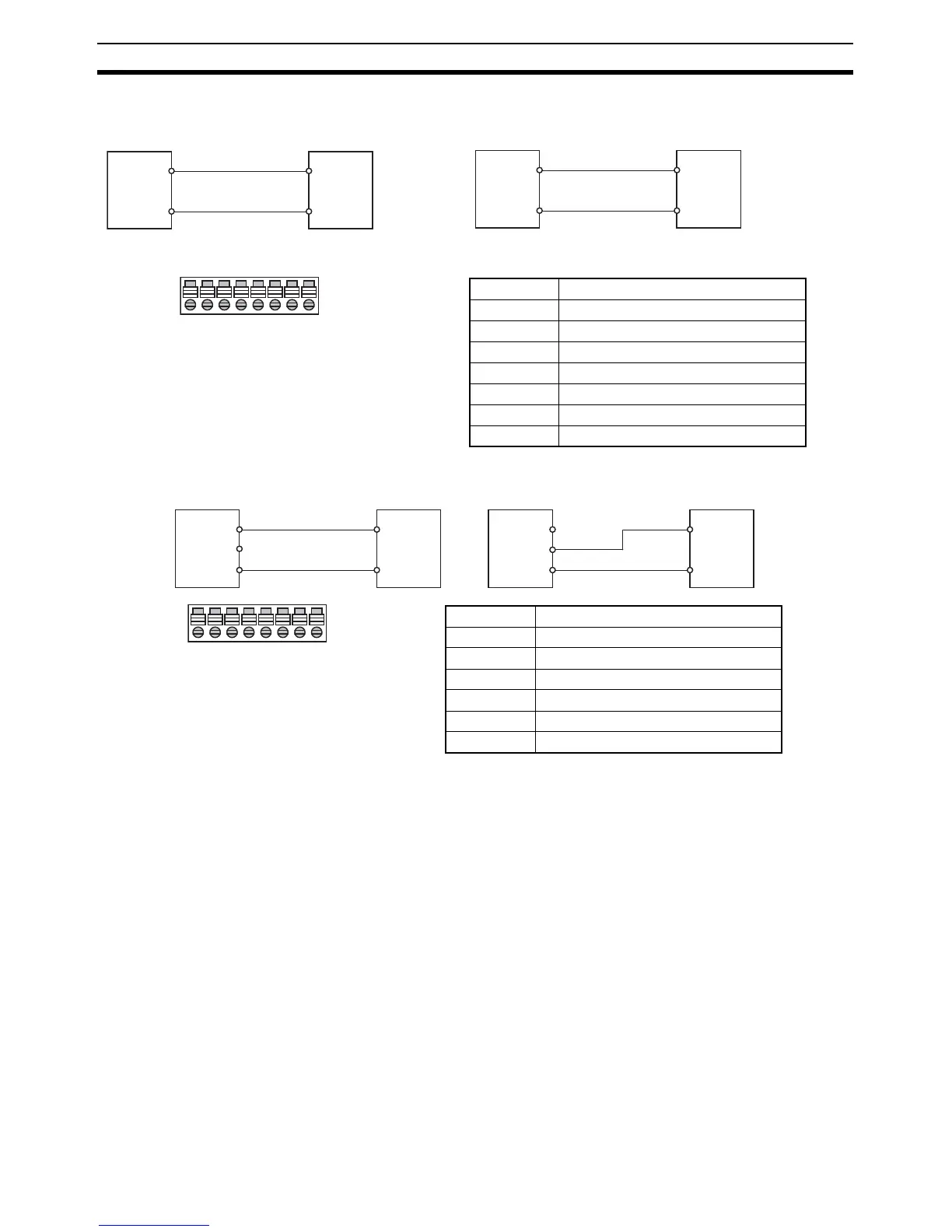
3. Wiring Analog I/O
Wiring Analog Inputs
Wiring Analog Outputs
Note (1) Use 2-conductor shielded twisted-pair cable for the I/O wiring, and do not
connect the shield.
(2) If an input is not being used, connect (short) the input’s + and − terminals.
(3) Wire I/O lines apart from power lines (AC power supply lines, three-phase
power lines, etc.).
(4) If noise is received from power supply lines, insert a noise filter in the
power supply input section.
(5) When noise disturbs the analog input/output cable, install the core as
shown below to improve anti-noise performance.
Recommended ferrite core
Ferrite core (data line noise filter): 0443-164151 (manufactured by Nis-
shin Electric Co., Ltd.)
+
COM
−
Analog
output
device
(voltage
output)
Turn OFF the input's Analog
Volta
ut Switch.
V IN/IIN
Analog
Input
Terminal
Block
+
COM
−
V IN/IIN
Analog
output
device
(current
output)
Turn ON the input's Analog
Voltage/Current Input Switch.
Analog
Input
Terminal
Block
VIN0/IIN0
COM0
VIN1/IIN1
XOM1
VIN2/IIN2
COM2
VIN3/IIN3
COM3
VIN0/IIN0 Analog input 1 voltage/current input
COM0 Analog input 1 common
VIN1/IIN1 Analog input 2 voltage/current input
COM1 Analog input 2 common
VIN2/IIN2 Analog input 3 voltage/current input
COM2 Analog input 3 common
VIN3/IIN3 Analog input 4 voltage/current input
COM3 Analog input 4 common
V OUT
COM
I OUT
V OUT
COM
I OUT
+
−
+
−
Analog
output
Terminal
Block
Analog
input
device
(voltage
input)
Analog
output
Terminal
Block
Analog
input
device
(current
input)
VOUT1
IOUT1
COM1
VOUT2
IOUT2
COM2
AG
AG
VOUT1 Analog output 1 voltage output
IOUT1 Analog output 1 current output
COM1 Analog output 1 common
VOUT2 Analog output 2 voltage output
IOUT2 Analog output 2 current output
COM2 Analog output 2 common
AG Analog 0 V