412
Analog I/O Units Section 7-4
Writing the Range Code
Write the range code to word n+1. A/D or D/A conversion begins when the
range code is transferred from the CPU Unit to the Analog I/O Unit. There are
eight range codes, FF00 to FF07, that combine both the analog input 1 and 2
and analog output signal ranges, as shown below.
• The voltage/current selection is made by switching the wiring.
• Write the range code to the Analog I/O Unit output word (n + 1) in the first
cycle of program execution.
• The Analog I/O Unit will not start converting analog I/O values until the
range code has been written.
• Once the range code has been set, it is not possible to change the setting
while power is being supplied to the CPU Unit. To change the I/O range,
turn the CPU Unit OFF then ON again.
• If a range code other than those specified in the above table is written to
n+1, the range code will not be received by the Analog I/O Unit and ana-
log I/O conversion will not start.
Range
code
Analog input 1 signal
range
Analog input 2 signal
range
Analog output signal
range
FF00 0 to 10 V 0 to 10 V 0 to 10 V/4 to 20 mA
FF01 0 to 10 V 0 to 10 V −10 to 10 V/4 to 20 mA
FF02 1 to 5 V/4 to 20 mA 0 to 10 V 0 to 10 V/4 to 20 mA
FF03 1 to 5 V/4 to 20 mA 0 to 10 V −10 to 10 V/4 to 20 mA
FF04 0 to 10 V 1 to 5 V/4 to 20 mA 0 to 10 V/4 to 20 mA
FF05 0 to 10 V 1 to 5 V/4 to 20 mA −10 to 10 V/4 to 20 mA
FF06 1 to 5 V/4 to 20 mA 1 to 5 V/4 to 20 mA 0 to 10 V/4 to 20 mA
FF07 1 to 5 V/4 to 20 mA 1 to 5 V/4 to 20 mA −10 to 10 V/4 to 20 mA
Analog I/O Unit
(m + 1)
(m + 2)
32 analog inputs
16 analog outputs
(n + 1)
"m" is the last allocated input word and
"n" the last allocated output word on
the CPU Unit or previous Expansion
Unit or Expansion I/O Unit.
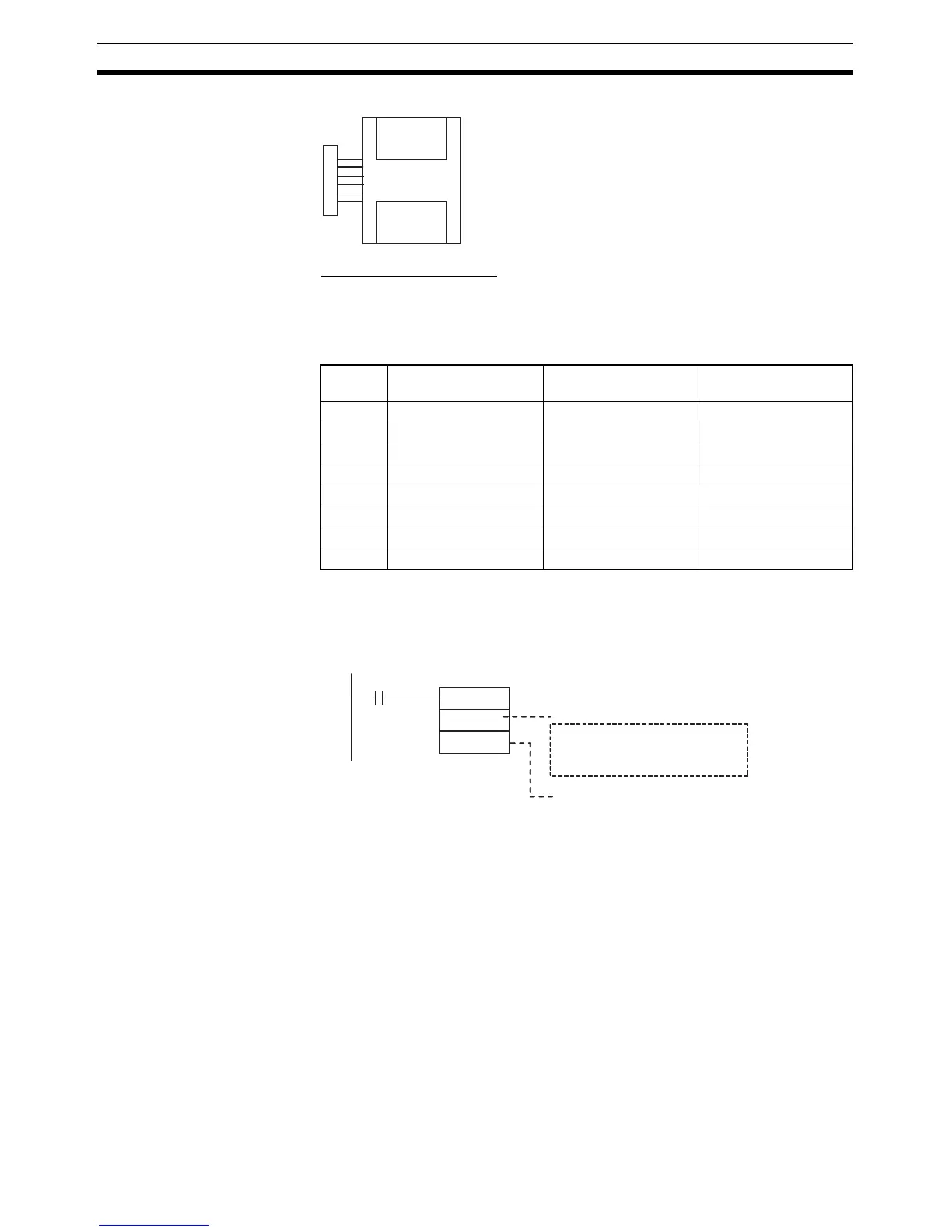
MOV(021)
FF02
(n+1)
A200.11
First Cycle Flag
Range code (4 digits hexadecimal)
Analog input 1: 1 to 5 V or 4 to 20 mA
Analog input 2: 0 to 10 V
Analog output: 0 to 10 V or 4 to 20 mA
Allocated out