413
Analog I/O Units Section 7-4
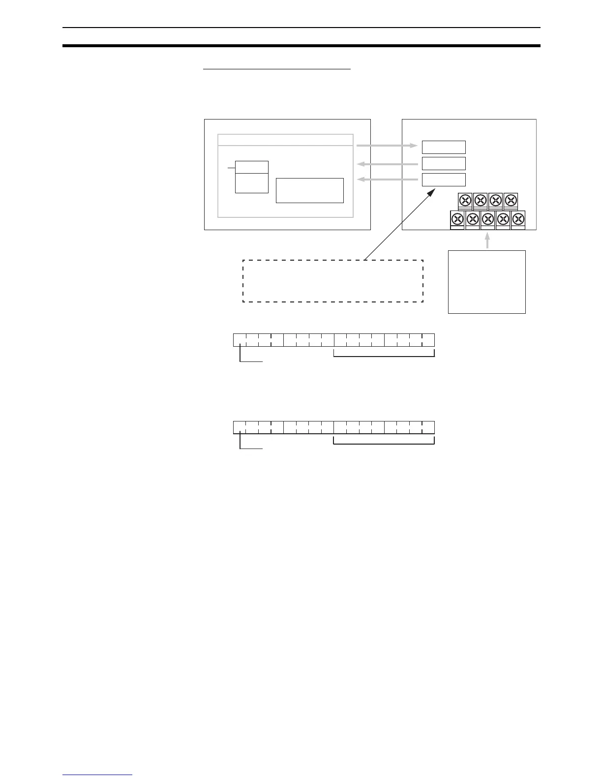
Reading A/D Conversion Tables
Data converted from analog to digital is output to bits 00 to 07 in words m+1
and m+2.
Note The Open-circuit Detection Flag is turned ON if the input signal range is set to
1 to 5 V or 4 to 20 mA and the input signal falls below 1 V or 4 mA. (Open cir-
cuits are not detected when the input signal range is set to 0 to 10 V.)
MOV(21)
MOVE instruction
Ladder program
Range code
Word n + 1
Word m + 1
Word m + 2
CPU Unit Analog I/O Unit
Writes the range
code. Reads the
conversion value.
Analog input 1
conversion value
Analog input 2
conversion value
"m" is the last input word and "n" is the last
output word allocated to the CPU Unit, or
previous Expansion Unit or Expansion I/O Unit.
Analog devices
· Temperature sensor
· Pressure sensor
· Speed sensor
· Flow sensor
· Voltage/current meter
m + 1
15
m + 2
15
00
07
07
00
Analog input 1
Open-circuit
Detection Flag
0: Normal
1: Open-circuit
Analog input 1 conversion value (00 to FF hex)
Analog input 2
Open-circuit
Detection Flag
0: Normal
1: Open-circuit
Analog input 2 conversion value (00 to FF hex)