423
Analog I/O Units Section 7-4
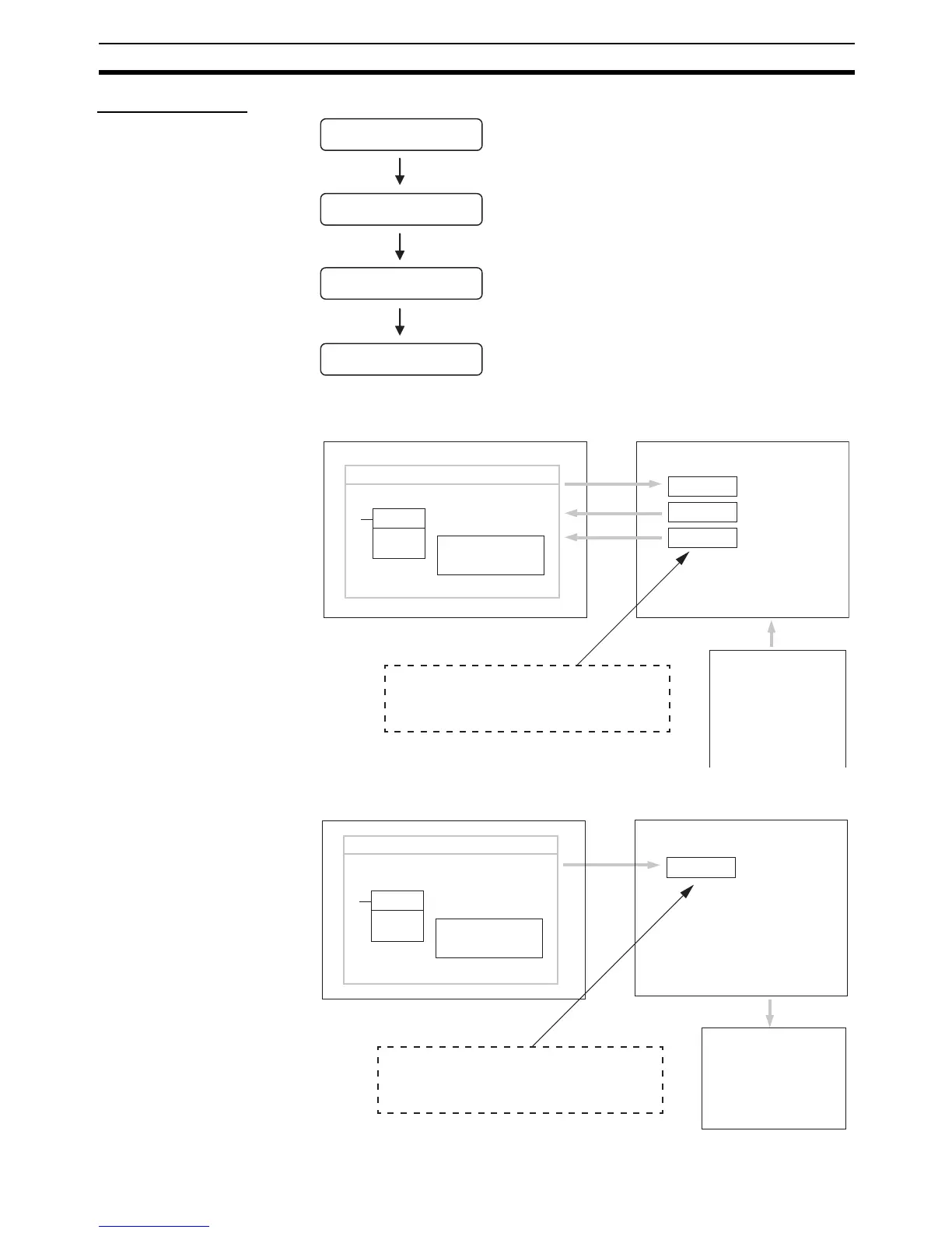
Using Analog I/O
Reading Range Code
Settings and A/D
Conversion Data
Writing D/A Conversion
Data
Connect the Unit.
Set the I/O ranges.
Wire the analog I/O.
Program operation in
the ladder program.
• Connect the Analog I/O Unit.
• Analog inputs: 0 to 5 VDC, 1 to 5 VDC, 0 to 10 VDC, –10 to
10 VDC, 0 to 20 mA, or 4 to 20 mA
• Analog output: 1 to 5 VDC, 0 to 10 VDC, –10 to 10 VDC, 0 to
20 mA, or 4 to 20 mA
• Set analog inputs as voltage or current inputs and set the
averaging function.
• Connect analog I/O devices.
• Write the range code.
• Analog inputs: Read converted data.
• Analog output: Write set values.
MOV(21)
MOVE instruction
Ladder program
Range code
Word n + 1
Word m + 1
Word m + 2
CPU Unit Analog I/O Unit
• Writes the range code.
• Reads the converted
values.
Analog input 0
converted value
Analog input 1
converted value
"m" is the last input word and "n" is the last
output word allocated to the CPU Unit or
previous Expansion Unit or Expansion I/O Unit.
Analog devices
• Temperature sensor
• Pressure sensor
• Speed sensor
• Flow sensor
• Voltage/current meter
• Other
MOV(21)
MOVE instruction
Ladder program
Word n + 1
CPU Unit Analog I/O Unit
(See note.)
• Writes the range code.
• Writes the set value.
Range code
Analog output set value
"n" is the last output word allocated to the CPU
Unit or previous Expansion Unit or Expansion I/O
Unit.
Analog devices
• Adjustment equipment
• Servo Controller
• Variable speed device
• Recorder
• Other