425
Analog I/O Units Section 7-4
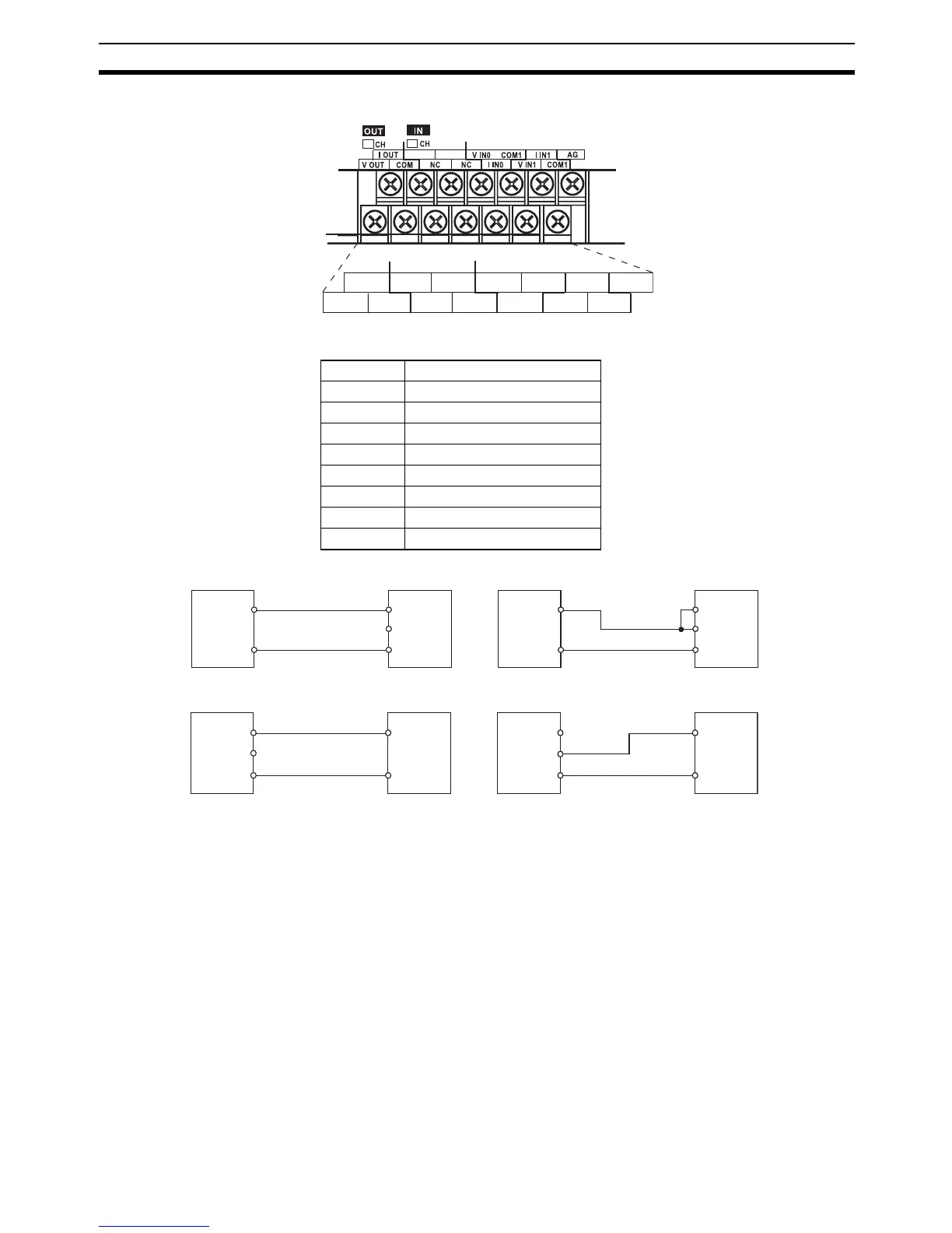
Terminal Arrangements
Note For current inputs, short V IN0 to I IN0 and V IN1 to I IN1.
Wiring for Analog Inputs
Wiring for Analog Outputs
Note (1) Use shielded twisted-pair cables, but do not connect the shield.
(2) When an input is not being used, short the + and − terminals.
(3) Separate wiring from power lines (AC power supply lines, high-voltage
lines, etc.)
(4) When there is noise in the power supply line, install a noise filter on the
input section and the power supply terminals.
I OUT V IN0
COM0
V OUT
COM I IN0
I IN1
V IN1 COM1
NC NC
AG
NC NC
NC
NC
V OUT Voltage output
I OUT Current output
COM Output common
V IN0 Voltage input 0
I IN0 Current input 0
COM0 Input common 0
V IN1 Voltage input 1
I IN1 Current input 1
COM1 Input common 1
V IN
COM
I IN
V IN
COM
I IN
Analog
device
with
voltage
output
+
−
+
−
Analog
I/O Unit
Analog
device
with
current
output
Analog
I/O Unit
V OUT
COM
I OUT
V OUT
COM
I OUT
Analog
device
with
voltage
input
+
−
+
−
Analog
I/O Unit
Analog
device
with
current
input
Analog
I/O Unit