453
DeviceNet I/O Link Units Section 7-7
LED Indicators
Handling Unit Errors If a communications error occurs while the slave is on standby, the appropri-
ate bit in word A436 will turn ON. The appropriate bit is determined by the
order in which the Expansion Units and Expansion I/O Units are connected.
The Unit nearest to the CPU Unit uses A436.00. Use these flags in the pro-
gram when it is necessary to detect errors.
Operating Procedure
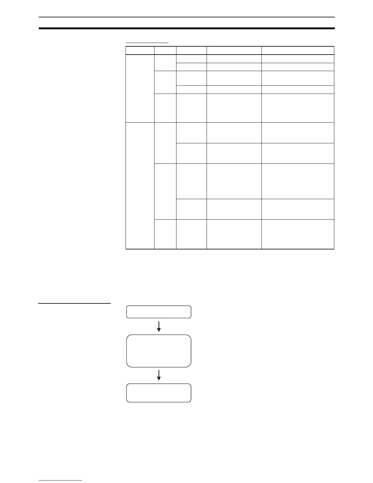
Indicator Color Status Condition Meaning
MS Green Lit Normal status • Normal status
Flashing Not set • Switch settings being read
Red Lit Fatal error • Fatal hardware error
(watchdog timer)
Flashing Nonfatal error • Incorrect switch settings.
--- OFF Power not supplied. • Power not supplied.
• Waiting for initialization to
start.
• Reset in progress.
NS Green Lit Online and commu-
nications estab-
lished.
• Network normal and com-
munications established.
Flashing Online and commu-
nications not estab-
lished.
• Network normal and com-
munications not estab-
lished.
Red Lit Fatal communica-
tions error
Unit has detected network
status preventing normal
communications.
• Node number duplications
• Bus OFF detected.
Flashing Nonfatal communi-
cations error
• Communications timeout
or communications error
for one or more slaves.
--- OFF Online and power
OFF.
Waiting for node number
check by master.
• Switch setting error.
• Power not supplied.
Connect the Unit.
Determine the node
number of the DeviceNet
I/O Link Unit and set the
rotary switches.
Wire the DeviceNet
transmission path.
• Connect the DeviceNet I/O Link Unit.
• The node number should be a unique number between
0 and 63.
• Use the DIP switch to set the DeviceNet I/O Link Unit fs
baud rate and the status of output data when a
communications error occurs.
• Connect the DeviceNet I/O Link Unit to a DeviceNet
transmission path.