562
Sample Application Section 9-12
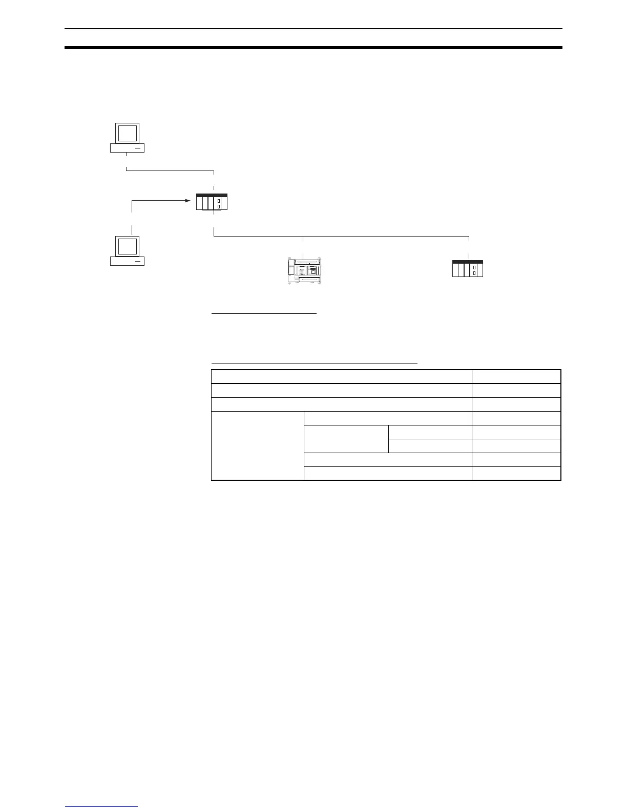
■ System Configuration Example 2: Using Routing Tables
In this example, an online connection is made via the Ethernet to a PLC on a
Controller Link network (PLC3 in the diagram below) from a CX-Programmer /
CX-Integrator connected to the Ethernet network.
Web Browser Setting
Same as for System Configuration Example 1.
CX-Programmer’s Change PLC Dialog Box
COMM
ERR
10BASE-T
100BASE-TX
(PC1)
(PC2)
(CP1H)
PLC1
PLC3PLC2
(CJ2H)
(CJ1H)
Ethernet #001
FINS Address
Net: #2, Node #3
FINS Address
Net: #1, Node #1
FINS Address
Net: #1, Node #3
Ethernet #002
192.168.2.100
192.168.1.2
192.168.1.1 192.168.1.3
Toolbus
192.168.2.3
Settings for target PLC (PLC1)’s Change PLC Dialog Box Setting
PLC name PLC2
Network classification PLC1
Network Tab FINS transmission source address 2
FINS destination Network number 1
Node address 1
Frame length 542bytes (default)
Response monitor time 5 seconds