563
Sample Application Section 9-12
Routing Table Settings and Transfer to Each PLC
Set the routing tables with CX-Integrator, and transfer them.
1,2,3... 1. Using CX-Integrator, connect online, and select Routing table - Settings.
Then create FINS local routing tables (a local network table and a relay
network table).
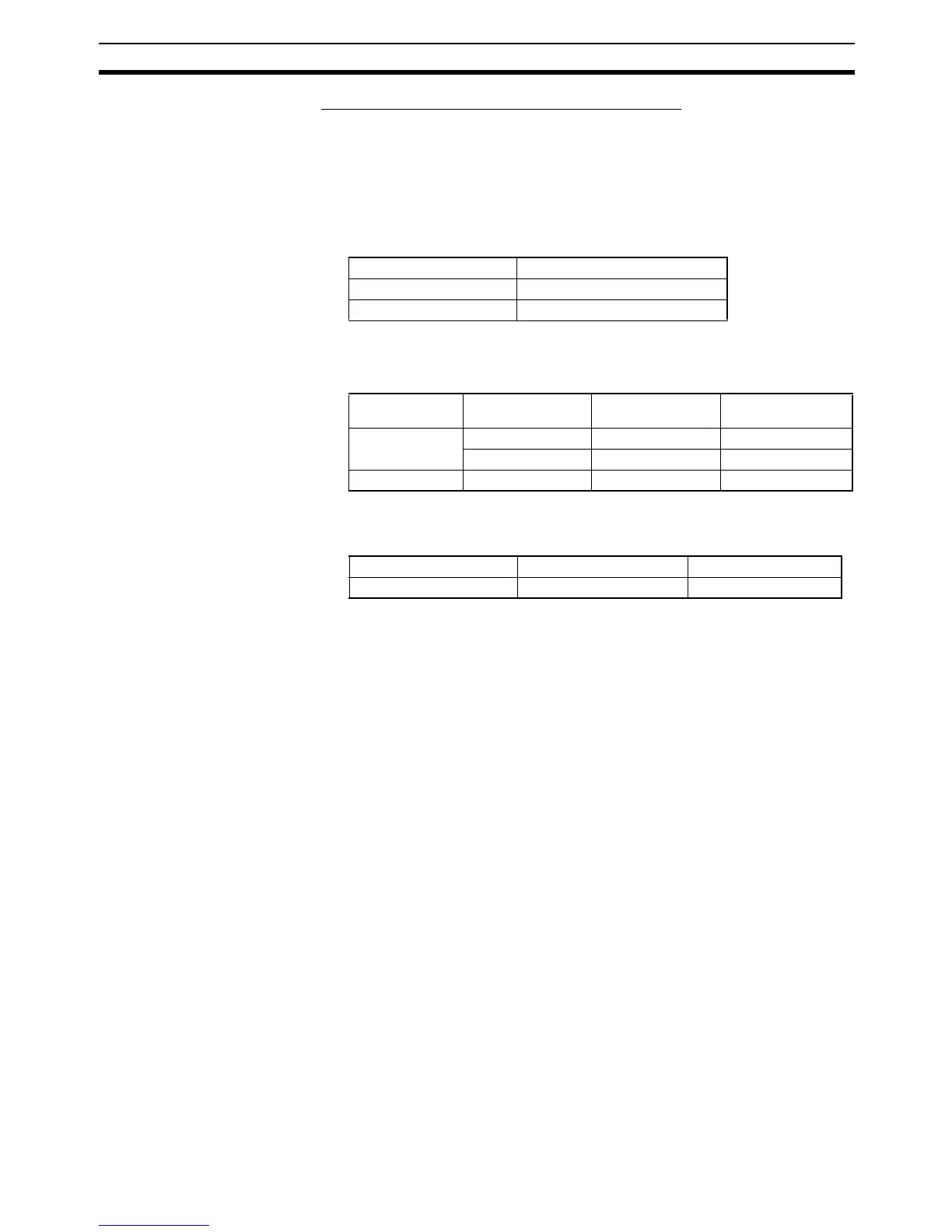
Example: PLC 1 Routing Table Settings
• Local Network Table
• Relay Network Table (None)
Example: PLC 2 and PLC 3 Routing Table Settings
• Local Network Table
• Relay Network Table
In order to relay from PLC2/3 to the final network number 2, it is neces-
sary to relay via node address 1 on relay network number 2.
2. Save the routing table file (File - Save local routing table file).
3. Select New from the Project Menu, and save with a file name. Then select
Add Device from the Project Menu. For each PLC, register a PLC with a
direct serial connection (node address: 0), and select it.
4. With CX-Integrator, select Open from the PLC Menu.
5. Select Routing table - Setup, read the saved file, and select Options -
Transfer to PLC. Click Yes to transfer the routing tables to the connected
PLCs.
Unit number Local network number
01
12
Option port No. I/O capacity Unit address Local network
number
Option port 1 14/20 252(0xFC hex) 1
30/40/60 253(0xFD hex) 1
Option port 2 30/40/60 252(0xFC hex) 1
Final network number Relay network number Relay node address
21 2