31
Connecting Programming Devices Section 1-3
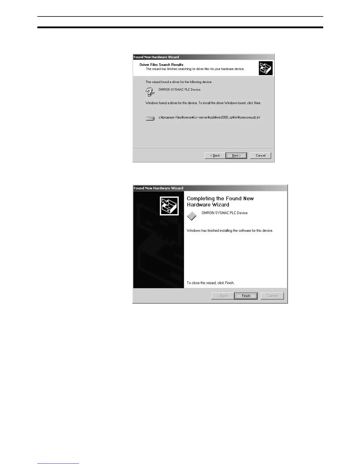
5. A search will be made for the driver and the following window will be dis-
played. Click the Next Button. The driver will be installed.
6. After the driver has been successfully installed, the following window will
be displayed. Click the Finish Button.