620
Auxiliary Area Allocations by Function Appendix C
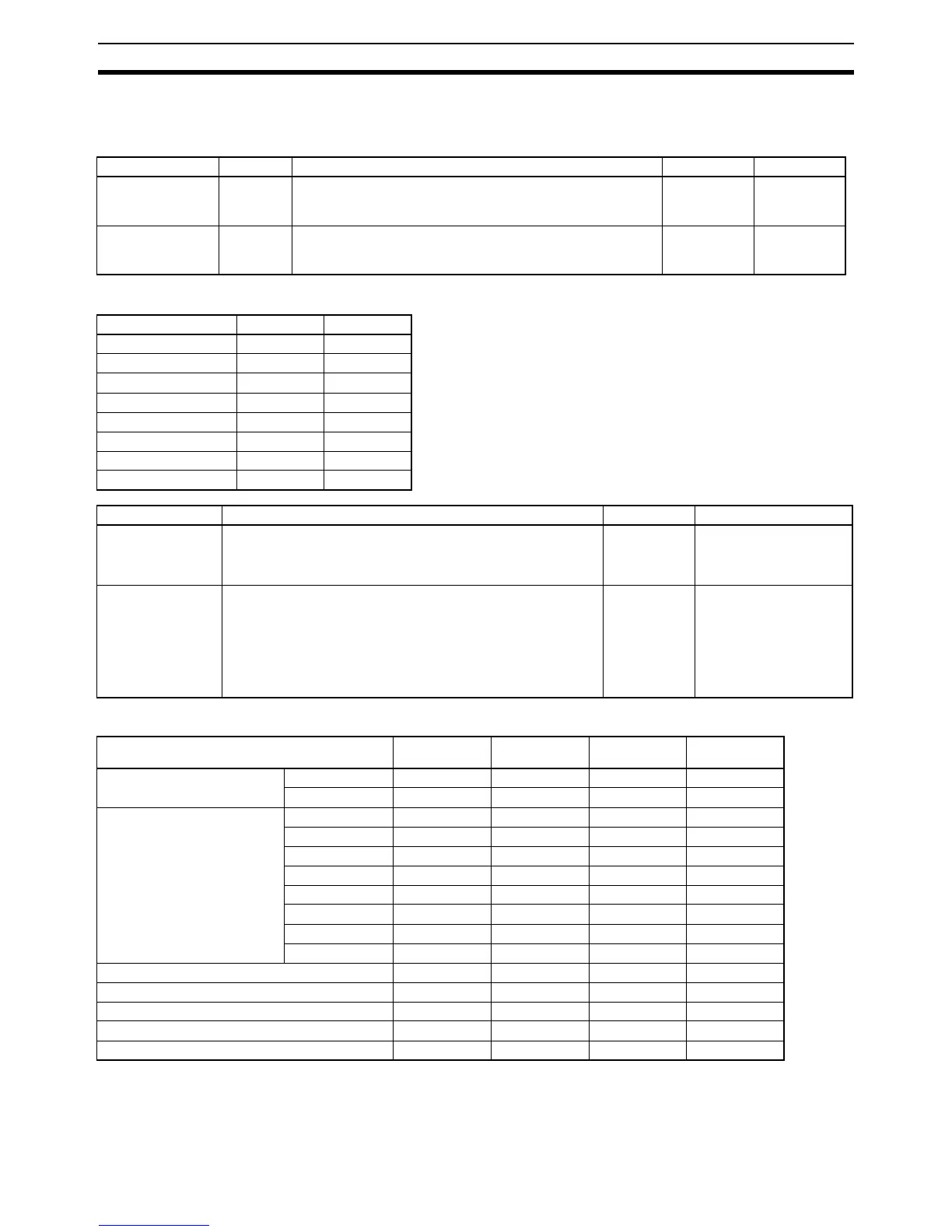
Built-in Inputs
Analog Adjustment and External Analog Setting Input
Input Interrupts, Interrupt Counters 0 to 7
High-speed Counters 0 to 3
Name Address Description Access Updated
Analog Adjustment
PV
A642 Stores the value set on the analog adjuster as a hexadecimal
value (resolution: 1/256).
0000 to 00FF hex
Read-only When analog
adjustment is
turned
External Analog
Setting Input PV
A643 Stores the value set from the external analog setting input as a
hexadecimal value (resolution: 1/256).
0000 to 00FF hex
Read-only
Interrupt counter Counter SV Counter PV
Interrupt counter 0 A532 A536
Interrupt counter 1 A533 A537
Interrupt counter 2 A534 A538
Interrupt counter 3 A535 A539
Interrupt counter 4 A544 A548
Interrupt counter 5 A545 A549
Interrupt counter 6 A546 A550
Interrupt counter 7 A547 A551
Name Description Access Updated
Interrupt Counter
Counter SV
Used for an interrupt input in counter mode.
Sets the count value at which the interrupt task will start. The corre-
sponding interrupt task will start when the interrupt counter has
counted this number of pulses.
Read/Write • Retained when power is
turned ON.
• Retained when opera-
tion starts.
Interrupt Counter
Counter PV
These words contain the interrupt counter PVs for interrupt inputs
operating in counter mode.
In increment mode, the counter PV starts incrementing from 0.
When the counter PV reaches the counter SV, the PV is automati-
cally reset to 0.
In decrement mode, the counter PV starts decrementing from the
counter SV. When the counter PV reaches the 0, the PV is automat-
ically reset to the SV.
Read/Write • Retained when power is
turned ON.
• Cleared when operation
starts.
• Updated when interrupt
is generated.
Item High-speed
counter 0
High-speed
counter 1
High-speed
counter 2
High-speed
counter 3
High-speed Counter PV Leftmost 4 digits A271 A273 A317 A319
Rightmost 4 digits A270 A272 A316 A318
High-speed Counter Range
Comparison Condition Met Flag
Range 1 A274.00 A275.00 A320.00 A321.00
Range 2 A274.01 A275.01 A320.01 A321.01
Range 3 A274.02 A275.02 A320.02 A321.02
Range 4 A274.03 A275.03 A320.03 A321.03
Range 5 A274.04 A275.04 A320.04 A321.04
Range 6 A274.05 A275.05 A320.05 A321.05
Range 7 A274.06 A275.06 A320.06 A321.06
Range 8 A274.07 A275.07 A320.07 A321.07
High-speed Counter Comparison In-progress Flag A274.08 A275.08 A320.08 A321.08
High-speed Counter Overflow/Underflow Flag A274.09 A275.09 A320.09 A321.09
High-speed Counter Count Direction A274.10 A275.10 A320.10 A321.10
High-speed Counter Count Reset Bit A531.00 A531.01 A531.02 A531.03
High-speed Counter Gate Flag A531.08 A531.09 A531.10 A531.11