622
Auxiliary Area Allocations by Function Appendix C
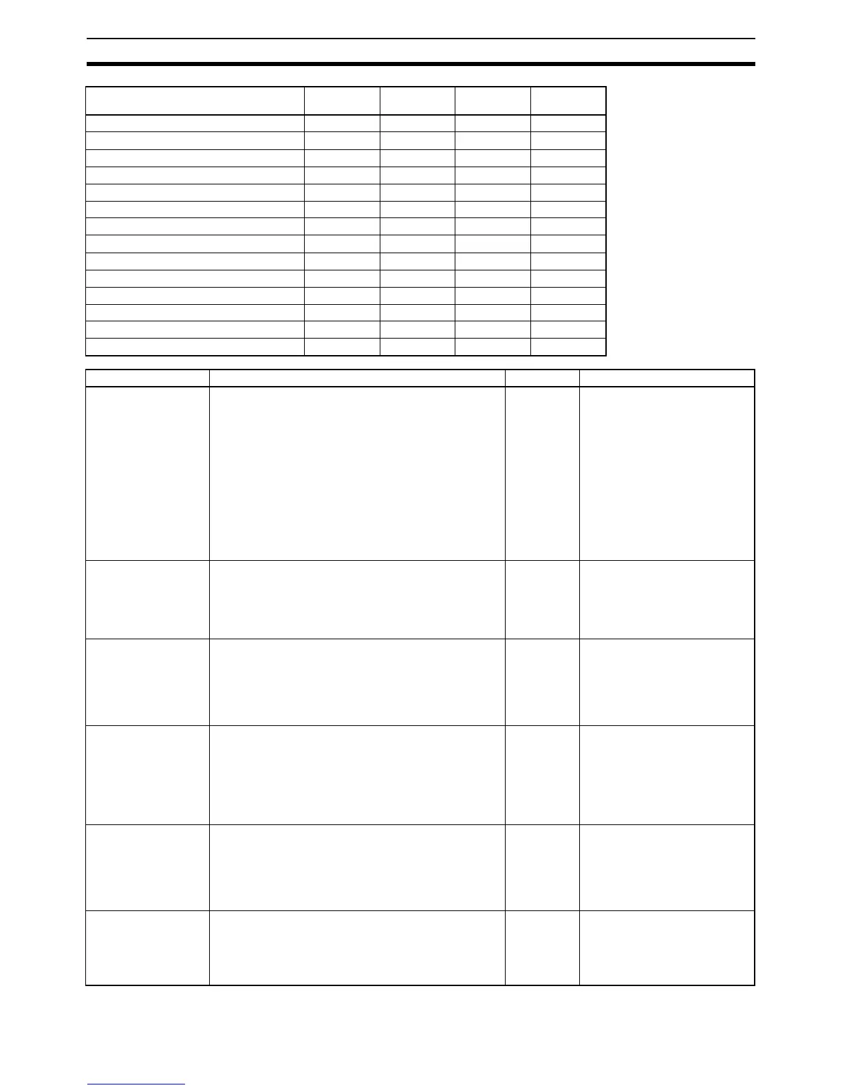
Pulse Output Accel/Decel Flag A280.00 A281.00 A326.00 A327.00
Pulse Output Overflow/Underflow Flag A280.01 A281.01 A326.01 A327.01
Pulse Output, Output Amount Set Flag A280.02 A281.02 A326.02 A327.02
Pulse Output, Output Completed Flag A280.03 A281.03 A326.03 A327.03
Pulse Output, Output In-progress Flag A280.04 A281.04 A326.04 A327.04
Pulse Output No-origin Flag A280.05 A281.05 A326.05 A327.05
Pulse Output At-origin Flag A280.06 A281.06 A326.06 A327.06
Pulse Output, Output Stopped Error Flag A280.07 A281.07 A326.07 A327.07
PWM Output, Output In-progress Flag A283.00 A283.08 A326.08 A327.08
Pulse Output Stop Error Code A444 A445 A438 A439
Pulse Output Reset Bit A540.00 A541.00 A542.00 A543.00
Pulse Output CW Limit Input Signal Flag A540.08 A541.08 A542.08 A543.08
Pulse Output CCW Limit Input Signal Flag A540.09 A541.09 A542.09 A543.09
Pulse Output Positioning Completed Signal A540.10 A541.10 A542.10 A543.10
Name Description Read/Write Updated
Pulse Output PV Contain the number of pulses output from the correspond-
ing pulse output port. PV range: 80000000 to 7FFFFFFF
hex (-2,147,483,648 to 2,147,483,647)
When pulses are being output in the CW direction, the PV
is incremented by 1 for each pulse.
When pulses are being output in the CCW direction, the PV
is decremented by 1 for each pulse.
PV after overflow: 7FFFFFFF hex
PV after underflow: 80000000 hex
Note If the coordinate system uses relative coordinates
(undefined origin), the PV will be cleared to 0 when
a pulse output starts, i.e. when a pulse output
instruction (SPED(885), ACC(888), or PLS2(887))
is executed.
Read-only • Cleared when power is turned
ON.
• Cleared when operation starts.
• Updated each cycle during over-
see process.
• Updated when the PV is
changed by the INI(880) instruc-
tion.
Pulse Output
Accel/Decel Flag
This flag will be ON when pulses are being output accord-
ing to an ACC(888) or PLS2(887) instruction and the output
frequency is being changed in steps (accelerating or decel-
erating).
OFF: Constant speed
ON: Accelerating or decelerating
Read-only • Cleared when power is turned
ON.
• Cleared when operation starts or
stops.
• Updated each cycle during over-
see process.
Pulse Output Over-
flow/Underflow Flag
This flag indicates when an overflow or underflow has
occurred in the pulse output PV.
OFF: Normal
ON: Overflow or underflow
Read-only • Cleared when power is turned
ON.
• Cleared when operation starts.
• Cleared when the PV is changed
by the INI(880) instruction.
• Updated when an overflow or
underflow occurs.
Pulse Output, Output
Amount Set Flag
ON when the number of output pulses has been set with
the PULS(886) instruction.
OFF: No setting
ON: Setting made
Read-only • Cleared when power is turned
ON.
• Cleared when operation starts or
stops.
• Updated when the PULS(886)
instruction is executed.
• Updated when pulse output
stops.
Pulse Output, Output
Completed Flag
ON when the number of output pulses set with the
PULS(886) or PLS2(887) instruction has been output.
OFF: Output not completed.
ON: Output completed.
Read-only • Cleared when power is turned
ON.
• Cleared when operation starts or
stops.
• Updated at the start or comple-
tion of pulse output in indepen-
dent mode.
Pulse Output, Output
In-progress Flag
ON when pulses are being output.
OFF: Stopped
ON: Outputting pulses.
Read-only • Cleared when power is turned
ON.
• Cleared when operation starts or
stops.
• Updated when pulse output
starts or stops.
Item Pulse output
0
Pulse output
1
Pulse output
2
Pulse output
3