688
Connections to Serial Communications Option Boards Appendix F
• If the I/O wiring and power cables must be placed in the same duct, they must be shielded from each other
using grounded steel sheet metal.
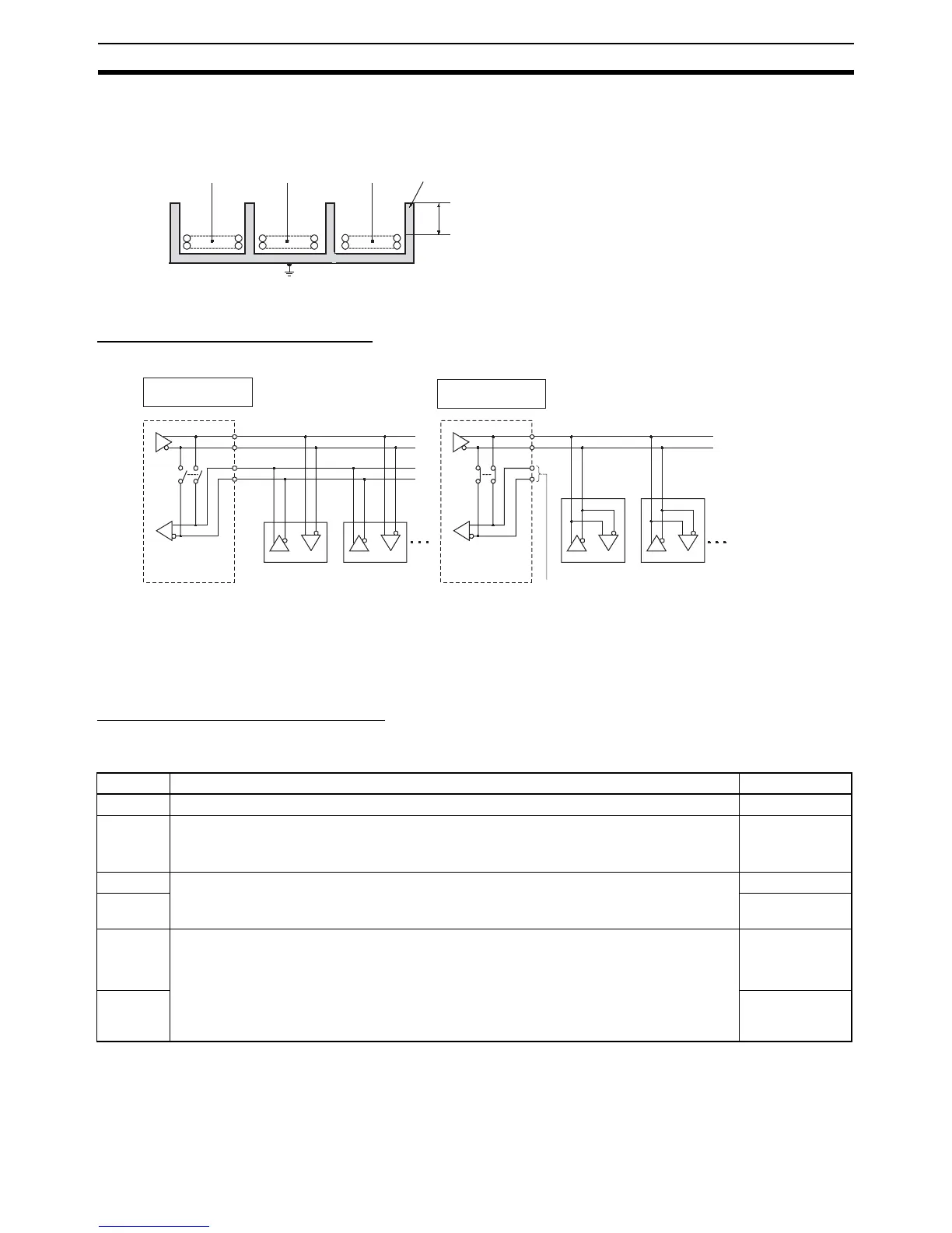
2-Wire and 4-Wire Connections
The transmission circuits for 2-wire and 4-wire connections are different, as shown in the following diagram.
Note (1) Use the same transmission circuit (2-wire or 4-wire) for all nodes.
(2) Do not use 4-wire connections when the 2/4-wire switch on the Board is set to 2-wire.
NT-AL001 Link Adapter Settings
The NT-AL001 Link Adapter has a DIP switch for setting RS-422A/485 communications conditions. When con-
necting the Serial Communications Option Board, refer to the DIP switch settings shown in the following table.
Note When connecting to a CP-series CPU Unit, turn OFF pin 5 and turn ON pin 6.
Communications
cables
PLC power supply
and general control
circuit wiring
Power lines
200 mm min.
Ground to 100 Ω or less.
Steel sheet metal
Example of 4-Wire
Connections
Example of 2-Wire
Connections
2/4-wire switch
(DPDT)
Option Board
2/4-wire switch
(DPDT)
Option Board
Not connected
Other Unit
Other UnitOther Unit
Other Unit
Pin Function Factory setting
1 Not used. Always set this pin to ON. ON
2 Built-in terminating resistance setting
ON: Connects terminating resistance.
OFF: Disconnects terminating resistance.
ON
3 2/4-wire setting
2-wire: Set both pins to ON.
4-wire: Set both pins to OFF.
OFF
4 OFF
5 Transmission mode (See note.)
Constant transmission: Set both pins to OFF.
Transmission performed when CTS signal in RS-232C interface is at high level:
Set pin 5 to OFF and pin 6 to ON.
Transmission performed when CTS signal in RS-232C interface is at low level:
Set pin 5 to ON and pin 6 to OFF.
ON
6 OFF