689
Connections to Serial Communications Option Boards Appendix F
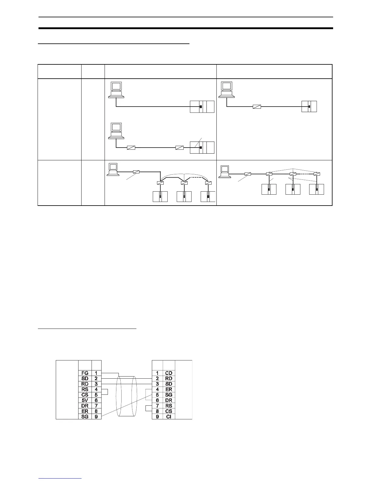
Connections for Host Link Communications
Port connections for Host Link communications are shown in the following table. Up to 32 nodes can be con-
nected for 1:N connections.
Note (1) Four-wire connections must be used for RS-422A/485 connections with Host Link communications.
(2) “Resistance ON” indicates the terminating resistance must be turned ON.
(3) “5-V power” indicates that a 5-V power supply is required for the Link Adapter. Refer to the Link
Adapter manual for details. A 5-V power supply is not required for a Link Adapter connected to an
RS-232C Option Board mounted on the CPU Unit because power is supplied from pin 6 of the con-
nector.
(4) The maximum cable length for RS-232C is 15 m. The RS-232C standard, however, does not cover
baud rates above 19.2 Kbps. Refer to the manual for the device being connected to confirm support.
Connection Examples
The connection examples in the remainder of this section show only the basic connection diagrams. We rec-
ommend that appropriate noise countermeasures be taken in actual applications, including the use of shielded
twisted-pair cables. Refer to Recommended RS-422A/485 Wiring Examples on page 707 for actual wiring
methods.
Host Computer Connections
1:1 Connections Using RS-232C Ports
• IBM PC/AT or Compatible Computers
Port Config-
uration
Schematic diagram, RS-232C ports Schematic diagram, RS-422A/485 ports
Computer to
PLC: C-mode or
FINS com-
mands
PLC to com-
puter: FINS
commands
1:1
Computer to
PLC: C-mode or
FINS com-
mands
1:N
NT-AL001
RS-232C
RS-232C
RS-422A/485
5-V