64
Specifications Section 2-2
Note Set using the MSKS instruction in direct mode or counter mode.
Input Specifications
Special High-speed Counter Inputs
Note The power supply at the line-driver must 5 V ±5% max.
CIO 1 00 Normal input
6
Interrupt
input 2
Quick-response
input 2
High-speed counter 3
(phase-Z/reset)
Pulse 3 origin input
signal
01 Normal input
7
Interrupt
input 3
Quick-response
input 3
--- Pulse 2 origin input
signal
02 Normal input
8
Interrupt
input 4
Quick-response
input 4
--- Pulse 1 origin input
signal (open collector)
03 Normal input
9
Interrupt
input 5
Quick-response
input 5
--- Pulse 0 origin input
signal (open collector)
04 Normal input
10
--- --- --- Pulse 1 origin proxim-
ity input signal
05 Normal input
11
--- --- --- Pulse 0 origin proxim-
ity input signal
Input terminal
block
Input operation setting High-speed counter
operation setting
Origin search
function
Word Terminal/
Bit
Normal
inputs
Interrupt
inputs
(See note.)
Quick-
response
inputs
High-speed counters 0 to 3
set to be used.
Origin search
function for pulse
outputs 0 and 1 set
to be used.
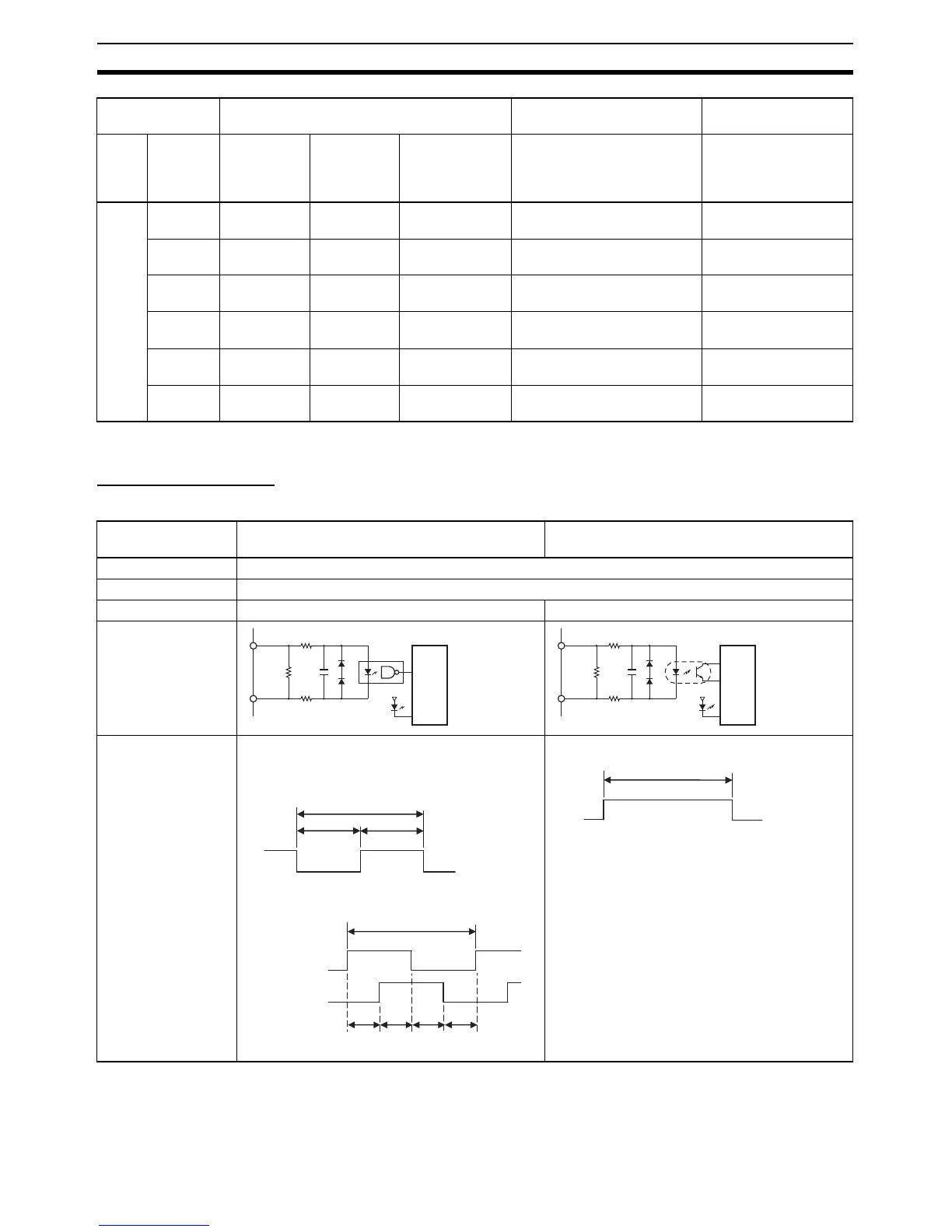
Item High-speed counter inputs, phase A and
phase B
High-speed counter inputs, phase Z
Input voltage RS-422A line-driver, AM26LS31 or equivalent (See note.)
Applicable inputs Line-driver inputs
Input current 10 mA typical 13 mA typical
Circuit configuration
ON/OFF delay • 1-MHz 50% duty ratio pulses, in phase-A or
phase-B pulse plus direction input mode, incre-
ment mode, or up/down mode
• Differential phase mode
•Phase Z
+
680 Ω
180 pF
330 Ω
330 Ω
−
Internal
circuits
180 Ω
+
560 Ω
6800 pF
180 Ω
−
Internal
circuits
OFF
ON
0.5 µs min.
0.5 µs min.
1 µs min.
OFF
ON
T1 T2
2 µs min.
OFF
ON
T3 T4
T1, T2, T3, T4: 0.5 µs min.
Phase A
Phase B
OFF
ON
90 µs min.