65
Specifications Section 2-2
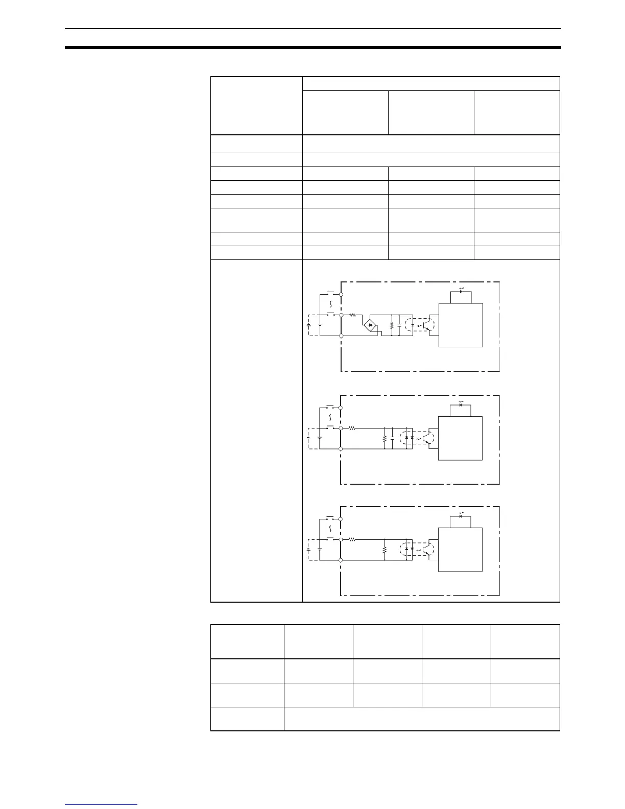
Normal Inputs
High-speed Counter Inputs
Item Specification
CIO 0.04,
CIO 0.05,
CIO 0.10, and
CIO 0.11
CIO 0.00,
CIO 0.01, and
CIO 1.00 to
CIO 1.03
CIO 1.04 and
CIO 1.05
Input voltage
24 VDC
+10%
/
−15%
Applicable inputs 2-wire and 3-wire sensors
Input impedance 3.0 kΩ 3.0 kΩ 4.7 kΩ
Input current 7.5 mA typical 7.5 mA typical 5 mA typical
ON voltage 17.0 VDC min. 17.0 VDC min. 14.4 VDC min.
OFF voltage/current 5.0 VDC max.,
1mA max.
5.0 VDC max.,
1mA max.
5.0 VDC max.,
1mA max.
ON delay 2.5 µs max. 50 µs max. 1 ms max.
OFF delay 2.5 µs max. 50 µs max. 1 ms max.
Circuit configuration
Differential
input mode
Pulse plus
direction
input mode
Up/down
input mode
Increment
mode
A0+/A0−
A1+/A1−
A-phase pulse
input
Pulse input Increment
pulse input
Increment
pulse input
B0+/B0−
B1+/B1−
B-phase pulse
input
Direction input Decrement
pulse input
Normal input
Z0+/Z0−
Z1+/Z1−
Z-phase pulse input or hardware reset input (Can be used as ordi-
nary inputs when high-speed counter is not being used.)
IN
IN
COM
3.0 kΩ
.4.3 kΩ
1000 pF
3.0 kΩ
1000 pF
IN
IN
COM
910 Ω
IN
IN
COM
4.7 kΩ
750 Ω
Input bits: CIO 0.04, CIO 0.05, CIO 0.10, CIO 0.11
Input bits: CIO 0.00, CIO 0.01, CIO 1.00 to CIO 1.03
Input bits: CIO 1.04, CIO 1.05
Input LED
Input LED
Input LED
Internal
circuits
Internal
circuits
Internal
circuits