66
Specifications Section 2-2
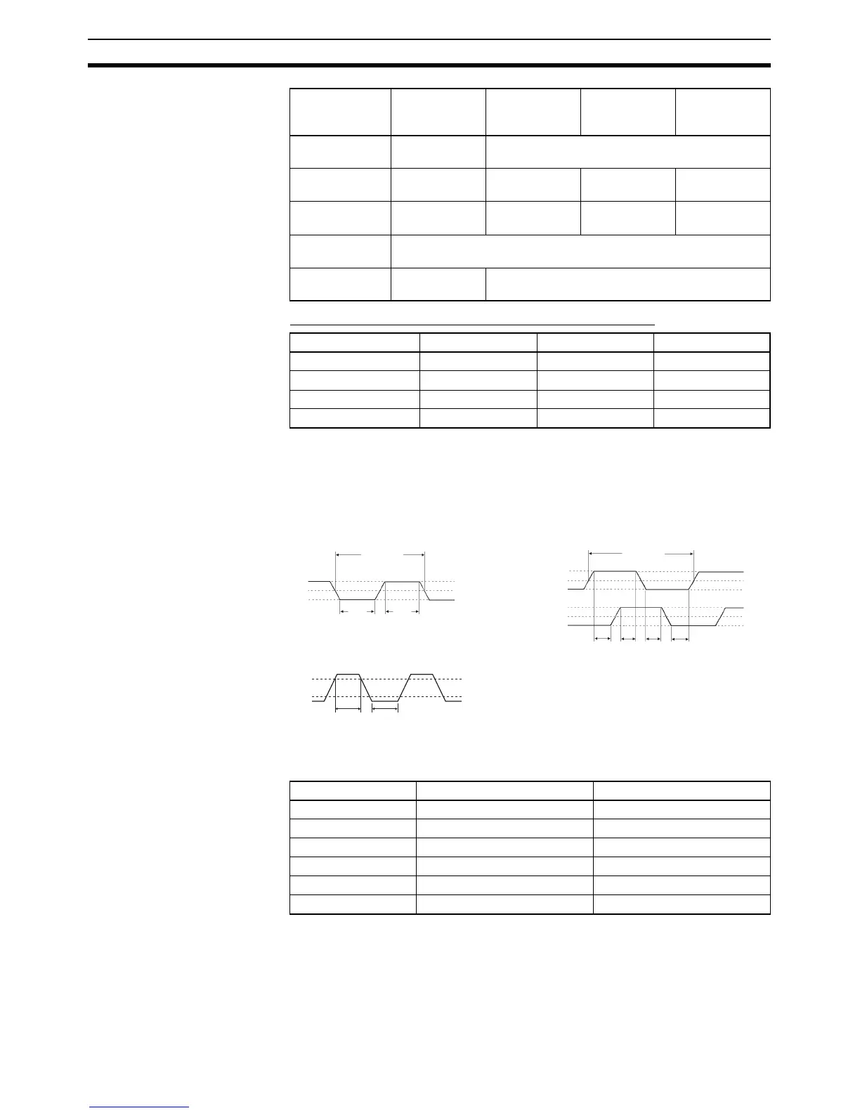
Inputs and Terminal Numbers for High-speed Counters
Input terminals: A0+/A0−/A1+A1− (Phase A)
B0+/B0−/B1+/B1− (Phase B)
Pulse plus direction input mode
Increment mode
Interrupt Inputs and
Quick-response Inputs
The following inputs can be used not only as normal inputs but also as inter-
rupt or quick-response inputs depending on the settings in the PLC Setup.
The ON/OFF response time is 8 ms for normal inputs, but it can be changed
in the PLC Setup to 0, 0.5, 1, 2, 4, 8, 16, or 32 ms.
Max. count fre-
quency
500 kHz (4×)1 MHz
0.04, 0.10 A-phase pulse
input
Pulse input Increment
pulse input
Increment
pulse input
0.05, 0.11 B-phase pulse
input
Direction input Decrement
pulse input
Normal input
0.01, 1.00 Z-phase pulse input or hardware reset input (Can be used as ordi-
nary inputs when high-speed counter is not being used.)
Max. count fre-
quency
50 kHz (4×) 100 kHz
Differential
input mode
Pulse plus
direction
input mode
Up/down
input mode
Increment
mode
Phase A Phase B Phase Z
High-speed counter 0 A0+/A0− B0+/B0− Z0+/Z0−
High-speed counter 1 A1+/A1− B1+/B1− Z0+/Z0−
High-speed counter 2 CIO 0.04 CIO 0.05 CIO 0.01
High-speed counter 3 CIO 0.10 CIO 0.11 CIO 1.00
90%
10%
50 µs
min.
50 µs
min.
ON
OFF
10.0 µs min.
ON
OFF
ON
OFF
ON
OFF
T
1
T
2
T
3
T
4
T
1
, T
2
, T
3
, T
4
: 2.5 µs min.
90%
50%
10%
90%
50%
10%
90%
50%
10%
2.5 µs
min.
2.5 µs
min.
20.0 µs min.
Up/down input mode Differential phase mode
Input terminals/bits: Z0+/Z1+/CIO 0.01/CIO 1.00
Phase A
Phase B
Input bit Interrupt inputs Quick-response inputs
CIO 0.00 Interrupt input 0 Quick-response input 0
CIO 0.01 Interrupt input 1 Quick-response input 1
CIO 1.00 Interrupt input 2 Quick-response input 2
CIO 1.01 Interrupt input 3 Quick-response input 3
CIO 1.02 Interrupt input 4 Quick-response input 4
CIO 1.03 Interrupt input 5 Quick-response input 5